1
Maintenance and Troubleshooting
SR-45i User’s Manual
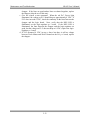
chopper. If the lines are good and no lines are shorted together, replace
the chopper (skip the rest of this test).
c. Give the system a start command. When the red D.C. Power light
illuminates, the voltage on P1-2 should drop to approximately 0 VDC. If
P1-2 does not read 0 VDC, check the continuity in the lines between the
chopper and the logic board. Next, verify that the REG LED is
illuminated on the logic-regulator p.c. board. If the REG LED is
illuminated, the lines between the chopper and the logic-regulator are
good, but the voltage on P1-2 does not drop to 0 VDC, replace the logicregulator p.c. board.
d. If P1-2 measured 0 VDC in step c above but there is still no voltage
between Torch Minus and Work Ground on the I/O p.c. board, replace
the chopper.
5-13