1
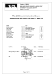
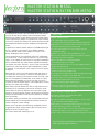
MASTER STATION MS741
1
2
3
4
5
6
26
7
8
25
24
9
23
10
11
12
13 14 15 16 17
18
19
20
22 21
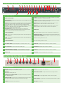
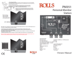
Front Panel Features
1
Power ON / OFF Switch
14
Cancel A - Front panel accessible preset to help elliminate feedback when talkback
microphone and speaker are operating simultaneously.
2
Elliptical Speaker - High efficiency elliptical speaker provides intelligible monitoring
of the intercom circuits.
15
Cancel B - Front panel accessible preset to help elliminate feedback when talkback
microphone and speaker are operating simultaneously.
3
Announce - Routes the output from the talkback microphone directly to a dedicated
socket on the rear panel to feed an external audio system. Announce signal appears
only on Master Station rear output. Announce may also be triggered remotely.
16
Sidetone A - When a headset is plugged in, the level of the user’s voice can be
adjusted in relation to other user’s voices on intercom circuit level.
4
Override - Triggers Tecpro LS200 and LS300 series paging loudspeaker to operate at
a preset level - independent of where the loudspeaker volume has been set.
This ensures important announcements are heard.
17
Sidetone B - When a headset is plugged in, the level of the user’s voice can be
adjusted in relation to other user’s voices on intercom circuit signal level.
5
Remote Mic Kill - Shuts down all open microphones on a selected circuit.
This feature is not compatible with original Tecpro designs which use mechanical switches.
All Series 2 products use electronic switching and will respond to ‘RMK’
18
Phones Level
6
Circuit A Select Button
19
Mic - Switches talkback microphone on and off. Latching and non-latching modes.
7
Call A - When Circuit A is selected, pressing the Call button makes all Call lights on
that circuit illuminate.
20
Headset Input / Output - Inserting a gooseneck microphone automatically mutes
the Master Station’s internal microphone. Plugging in a headset mutes both the internal
microphone and the loudspeaker.
8
Call B - When Circuit B is selected, pressing the Call button makes all Call lights on
that circuit illuminate.
21
B - Indicates auxiliary selected for circuit B.
9
Circuit B Select Button
22
A - Indicates auxiliary selected for circuit A.
10
Aux Selector Switch - Directs auxiliary audio to circuit A, B, A and B or none,
23
Overload B - Indicates excessive current draw on circuit B intercom line.
11
Aux Level Control - Controls the level of the auxiliary signal.
24
Termination Off - Indicates audio termination is disabled.
12
Circuits Independent / Link B to A - Using the toggle switch, circuit B may be
linked to circuit A to form a single ‘super’ circuit with double the drive capacity .
25
Overload A - Indicates excessive current draw on circuit A intercom line.
13
Speaker Level
26
Front Panel - Brushed, anodised aluminium curved extrusion.
MASTER STATION MS741 (rear)
1
2
3
4
5
6
7
8
9
10
11
12
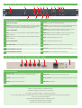
Rear Panel Features
1
Mic Input - Additional 3-pole A gauge 6.35mm jack for unbalanced low impedance
microphone. Phantom power not available on this input.
7
+
8
Circuit A - XLR3 intercom circuit connectors.
2
Aux Input
Balanced XLR3 auxiliary audio input.
9
Master Station Extender - 15-way D-SUB connector for linking to ME742.
3
Auxiliary mic / line selector switch - Three position switch: LINE, MIC and MIC
with +48V phantom power.
10
Speaker Output - 2-pole A gauge 6.35mm socket for 8 ohm 2W speaker.
4
Announce Output - 6-pin DIN socket. Carries balanced line level announce signal.
Also supplies relay contact for GPI and input for remote announce trigger.
11
Power Connector - IEC fused inlet for world-wide operation. 90-260 VAC, 50-60Hz.
5+
6
Circuit B - XLR3 intercom circuit connectors.
12
Rear Panel - Alocrom finish.