1
<
<
W
M.T
O
.C
W
00Y
1
M.T
.
O
W
C
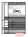
■ Specifications
WW .100Y.
.TW
M
O
W
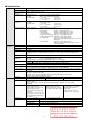
PV input
Input type
Thermocouple, RTD, DC current, DC
voltage (Selected by model. See Table 1.)
WW .100Y.C M.TW
.TW
Sampling time
0.5s
M
WW 00Y.CO .TW
.CO
Process variable (PV) -1999
to +9999 orW
-199.9 to +999.9
Y
W
0
T
.
0
correction
W.1 Y.COM W
OM
W.1 Thermocouple
W(under
C
.
W
W
Input bias
current
input:
0.2µA
or
less
Y
W
00 conditions)
0 input: M.T
W
M.T
.1standard
.10RTD
Approx. 1mA (flowed
from A-terminal)
O
W
O
W
C
.
Y or less .TW
Y.C input: .TW 0 - 1V range:
WW .1001µA
WW .1DC
00voltage
M
.TW
M
0 - 5V, 1 - 5V range:
3.5µA orO
less
W
M
O
W
.orCless
O
W
C
.
Y
W
0
10V
range:
7µA
C
W
.
0
Y
W
.TW
W
0
0
Y
W
T
.
1
0
0
T
M
.
.
1
0
M
.
O
1
W
Effect of wiring
0.2µV/Ω or less
Oinput:
WThermocouple
.C
OM
W
W.
W
input:
Wresistance WW RTD
00Y
0Y.C M.TW±0.05%FS/Ω orWless
Y.C
1
0
0
T
M.T
.
.
1
0
.
O
1
DC voltage input:
0 - 1V range:
1µV/Ω or C
less
W
M
.
O
W
W
Y. less .TW
.CO .TW
0 - 5V, 1 - 5V range:
WW 3.5µV/Ω
WW .100Y.C M.TW
100 ororless
M
.
00Y
0
10V
range:
7µV/Ω
1
W
M
.
O
W
.CO .TW
W
C
.
Y
W
W
0
Y
W
WW 00Y.CO .TDisplay
W at burnoutW Thermocouple
Upscale + alarm display (AL01)10
M (AL01)
.
.100 inputOM.TRTD
M
.1
RTD
input
burnout:
Upscale + alarm
W
.COdisplay
O
WW
W
C
W
.
Y
W
C
W
.
0
Y
W
W
A-wire
burnout:
Upscale
+
alarm
display
(AL01)
.T
W
0
0
Y
W
T
.
1 + alarm display
0
M
.
.T
1
00
M
.
O
1
W
B-wire
burnout:
Upscale
(AL01,
M
.
O
W
O
W
WAL03)
Y.Cdisplay (AL01,
WWUpscale
T
C-wire
burnout:
+0
alarm
AL03)
.
0
WW .100Y.C M
TW
.
1
WW .100Y.C M.TW
M(AL01, AL03)
. + alarm display
O
2- or 3-wire burnout:
Upscale
W
O
W
C
O
W
Y. display (AL02)
and
Downscale0+0alarm
W short-circuit:
WW
.TW
WW .100Y.C A.TB-wire
1 + alarm display
WW .100Y.C M.TW
M
.
M
Aand
C-wire
short-circuit:
Downscale
(AL02)
O
W
O
W
O
W
W
voltage
+0alarm
(AL02)
0Y.CdisplayM
WDownscale
.TW
WW .100Y.C DCM
.TWinput:
WW .100Y.C M.TW
.
However,
a1voltage input
ranging from 0 to 10V cannot
O
W
O
W
.C
O
W
W
be W
detected.
W
00Ydisplay (AL02)
WW .100Y.CDC current
.TW
1
WW .100Y.C M.TW
M.T
.
input:
Downscale
+
alarm
M
O
W
O
W
.Cranging .from
O
W
However,
input
Y
WW a current
TW0 to 20mA
WW .100Y.C M.TW
100
WW .100Y.C M.TW
M
.
cannot be detected.
O
W
O
.C
W display)
W
W
WW LED00(PV:
COSP indication
Indications
method 4-digit, W
7-segment
Upper green
W SP: Lower
Y.C
Worange
W
00Y
Y.PV,
Tdisplay,
.
1
0
WW
T
M.T
.
.
1
0
M
.
and setting
O
1
W
M
.
Number
of
setting
points
Max.
4
points
O
W
C
W
W
.CO method
Y.Cdigit .TW
WW .100Y.
.TW
key operation
0at0each
WW .100YSetting
M
.TW <, , or W
1
M
.
O
W
M
O
W
O
W
Setting
1. W
WW .100Y.C M.TW
0Y.C M.TW
Y.C range .TW See Table W
0
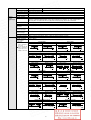
WW .100Indication
1
.
O
±0.5%FS±1 digit
W
M
O
Oaccuracy
W
WW
W is ±1%FS±1
In the negative
of the thermocouple,
accuracy
digit (at an0ambient
0Y.C temperature
Y.C the.T
WW
.TWof
0
Warea
1
0
WW .100Y.C M.TW23±2°C).
M
.
1
M
.
O
W
W
WW 00Y.CO .TW
.CO
WW .100Y.C M.TW
See Table 1. W
WW .1Indication
1
00Y rangeM.TW
M
.
and
Thermocouple input:WW1°C
O
WW 00Y.CO .TW
W Indication
.CO .TW
C
.
Y
W
W
W
0
Y
W
setting
1°C,
(depending on the type of input)
W
M
.1
.TRTD input:
100.1°C
00 units
OM range): 1, 0.1, 0.01, 0.001
W.input
voltage input/DC current
(programmable
WW 00Y.CO .TW
W.1 Y.COM DCW
C
.
W
W
Y
W
W
.Tvalue of setting value (SP)Wlimit
00 to upperM
W
T limit LowerW
.1
Settling
limit value of
range
limit
OM
M.Lower
.100value (SP)
O(SP)
Wof.1setting
C
.
O
W
W
C
W
.
Y
W
C
limit
Upper
limit
Lower
limit
value
value
limit
to
upper
limit
value
of
range
W
.
Y
W
W
.T
0Y method MDigital
WW Function
M.T
.100
.TW4-digit, 7-segment
100 (Common
0display
M
.
O
1
W
.
LED
indication
to
the
PV
display,
displayed
in
green)
O
W
W
.C
.CO EV1,.TEV2,
WW .100Y.C M.TW
W EV3: Red LED
WW
.TW
lamp indication
00Y
WWStatus.indication
1
00Y
M
.
1
M
O Green LED lamp indication
(READY), MAN
O0T1, 0T2 (control output), RDY
WW 00Y.CO .TW
W
.C(power):
WW
C
W
.
Y
W
W
W
0
Y
W
T
.
W Display selection
T variable (PV), Setting value .(SP),
M
.1 event remaining
Process
Time
10 Control output
00
M value, Heater current value,
M.SP
WW 00Y.CO .TW
W.1 Y.COtime,
No.
WW 00Y.CO .TW
W
W
W
W
WKey lock .100
Selected
W.1 Y.COM W
M.Tfrom the following threeWmethods:
W.1 Y.COM W
O
W
W
C
•
Key
lock
is
activated
in
all
modes.
.
W
W
W for operationW
.T setting mode/SP/event.W.100
W
M.T
.Tonly
100 andOparameter
00Y • Operable
indications .SP/EV/UF
M
O
1
M
.
W
C
O
W
.C
•C
Operable
only for operation indications
WW .100Y.
.TW
WW SP/EV/UF.
.TW
00Y
WW .100Y.The
M
.TW
1
M
.
O
W
Password
data
is protected by setting the password.
M
O
W
O
W
W
Y.C
WW
W
0Y.C(For SSR
Y.C
WWVoltage
TW
Control output Output
type
Relay
contact
pulse
drive)
Current.100
.
0
0
WW
T
M.T
.
1
0
M
.
O
1
W
M
.
O
W
C
.
O
W
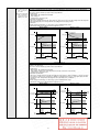
Control method
Selected
following three methods:
.C from the
WW .100Y
.TW
WW .100Y.C M.TW
WW .100• Y
ON/OFF control
M
.TW
O
W
M
O
W "Rationaloop PID (Ra-Pid)" and "Just-FiTTER")
O
with fixed PID value (PID control
using
W • Control
WW .100Y.C M.TW
W
Y.C
WW .100Y.C M.TW
WW .10• 0Self-tuning
T
.
O
W
W 19Vdc±15%
OM
W
.CO .TW
Y.C
Output ratingWW Output .rating:
Open
Output type: WW
Wvoltage:
C
0
Y
W
0
0
Y
W
0 outputMNO.Tside)
W
M.T
.1
Internal resistance:
0 to 20mAdc or 4 to 20mAdc
10 82Ω±0.5%
0(Control
M
.
O
1
W
.
O
W
C
W 250Vac/30Vdc,
load)
Allowable
24mAdc
Allowable load resistance:
.C
W current:0Max.
.CO 3A (resistive
WW .100Y.
0YMax.
Wcurrent
.TW
WW .(Control
TW
M.T
Leak
at.1
OFF:
100µA
Max. 600Ω
.side)
00Y output NC
M
O
1
W
M
O
W
C
.
O
W
W
C
250Vac/30Vdc,
load)
Output
±0.5%FS
W accuracy:
0Y
W
.
Y.C 1A (resistive
WW .100Y.
.T(However,
WW Service
0 to 1mA ±1%FS) .10
.TW
00life:
M
OM
1
W
M
.
O
W
C
.
50,000 cyclesC
orO
more on NO side
W
W
C
.
Y
W
W
Y
W
Y. more .onTW
W
WW 100,000
M
.100
M.T
.100
100cycles orO
W
M NC side
.opening/closing
O
W
Min.
specifications:
.CO
W
W
C
.
Y
W
C
W
.
0
Y
W
W
W
0
Y
W
.T
W 5V, 100mA
.100
W.1 Y.COM
.100 5 to 120OM.T
OM
W
W
W
C
Cycle time (s)
0.1,
0.25,
0.5,
1
to
120
–
.
W
C
W
Y
W
W
0Y. (%FS) M0.1.TtoW999.9
WW
.100
M.T
.100
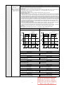
PID control
Proportional
W
.10band
O
W
O
W
W
C
W I = 0) 00Y.
W
W time 0(s)0Y.C 0 to.T9999
W (PD operationWwhen
.TW
WIntegral
1
M
.
1
M
.
O
W
Derivative
time
(s)
0
to
9999
(PI
operation
when
D
=
0)
O
W
.C
WW .100Y.C M.TW
WW set (%)
.toTW
Manual
-10.0
110.0 (only when I = 0)
00Y
1
M
.
O
W
O
W
WW .100Y.C
WW .100Y.C M.TW
W
O
W
WW
WW .100Y.C M.TW
O
W
WW .100Y.C M.TW
O
W
WW .100Y.C
W
2
WW