1
INTRODUCTION
TECHNICAL MANUALS
TECHNICAL SPECS
MICROMODULE
MOTOR CONTROLLER
QUICK INSTALLATION GUIDE
v1.2
CAUTION
NORMAL OPERATING VOLTAGE
250V-A.C.,50Hz
MAXIMUM LOAD
1.8 HP
FREQUENCY RANGE
868.42MHz
WIRELESS RANGE
Up to 30m line of sight
This device is using a radio signal that passes through walls,
windows and doors. The range is strongly influenced by local
conditions such as large metal objects, house wiring, concrete,
furniture, refrigerators, microwaves and similar items. On
average, the indoor range is approximately 30 meters.
Do not expose this product to excessive heat or moisture.
Prevent long term exposure to direct sunlight.
Do not attempt to repair this product. If the product is damaged
or if you are in doubt about the proper operation, take the
product back to the place of purchase.
Do not clean the product with any liquid.
TRADEMARKS
Zipato and the Zipato logo are registered Trademarks. All
other product names mentioned herein may be trademarks or
registered trademarks of their respective companies.
NOTICE
Although Zipato has attempted to ensure the accuracy of the
content of this manual, it is possible that this document may
contain technical inaccuracies, typographical, or other errors.
Zipato assumes no liability for any error in this publication, and for
damages, whether direct, indirect, incidental, and consequential
or otherwise, that may result from such error, including, but not
limited to loss of data or profits. Zipato provides this publication
“as is” without warranty of any kind, either express or implied,
including, but not limited to implied warranties of merchantability
or fitness for a particular purpose. The published information in
the manual is subject to change without notice. Zipato reserves
the right to make changes in the product design, layout, and driver
revisions without notification to its users. This version of the
Installation guide supersedes all previous versions.
ELECTROMAGNETIC COMPATIBILITY
In proper state and when operated properly, the product complies
with all the requirements in respect of interference radiation
according to EN 301 489-17, EN 301 489-1 and EN 300 328. The
connections conducting HF signals must neither be manipulated
nor damaged.
TAKE CARE OF YOUR SAFETY
Display extreme caution when using ladders or steps, please
follow manufacturer’s instructions. Be careful when using hand
and power tools and follow the manufacturer’s guidelines when
using them. Take care that the correct tools are used. Wear
goggles or protective clothing where required.
DANGER
RISK OF ELECTROCUTION
All work on the device should only be carried out by trained and
skilled electricians. Observe the country-specific regulations.
CAUTION
The connected devices and the flush-mounted receiver can
become damaged if devices are operated that do not correspond
to the technical specifications (see technical data).
DANGER
RISK OF FATAL INJURY FROM ELECTRIC CURRENT.
The device has no basic insulation and must therefore be installed
in a way that protects against accidental contact.
DANGER
RISK OF FATAL INJURY FROM ELECTRIC CURRENT.
When installing a wall plate, the distance between the cover’s
fixing brackets or screws and the connections of the flushmounted MicroModule Motor Controller must be at least 4
mm once installed. If the distance is less than 4 mm, a deeper
installation box must be used. The fixing brackets or screws of the
cover must not press against the housing. Only insulated tools may
be used for operation on the device, e.g. an insulated phase tester.
we make every home smart
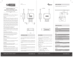
FIGURE 2 Connect with 1 Gang Push Button Switch
MM MOTOR
CONTROLLER
FRONT SIDE
Terminal
block
TECHNICAL DETAILS:
NORMAL OPERATING VOLTAGE
MAXIMUM LOAD
FREQUENCY RANGE
WIRELESS RANGE
STORAGE TEMPERATURE
STORAGE HUMIDITY
OPERATING TEMPERATURE
OPERATING HUMIDITY
250V - A.C. 50Hz
1.8HP
868.42MHz
Up to 30m line of sight
-5 ° C to +65 ° C
10% to 70%
0 ° C to 50 ° C
30% to 80%
ROUTING SLAVE
This Z-Wave product will be used as slave. Slave nodes are
nodes in a Z-Wave network that receive commands and perform
actions based on the command. A routing slave can route Z-Wave
messages to other nodes in the network.
This device is always awake and does not go to sleep mode because
it is an AC powered device. This device can act as a wireless
repeater to forward commands for another device in the Z-Wave
network to expand the range of the network. This function works
for every Z-Wave device from any manufacturer when included into
the same Z-Wave network.
Indicator
light
MM MOTOR
CONTROLLER
BACK SIDE
Push
button
FIGURE 3 Connect with 2 Gang Push Button Switch
FIGURE 1
BASIC OPERATIONS
The MicroModule Motor Controller can be remotely controlled.
The MicroModule Motor Controller can be add/remove from the
network by continuously switch on and switch off the external
switch 3 times quickly.
The MicroModule Motor Controller’s indicator light will indicate
the status of the MicroModule Motor Controller.
MOUNTING
NETWORK WIDE INCLUSION
When the MicroModule Motor Controller is not yet included
in a Z-Wave network, NWI will be started automatically for
30 seconds when the MicroModule Motor Controller is power ON.
Make sure your Z-Wave controller is in the correct operating mode
(inclusion).
NORMAL INCLUDE OR EXCLUDE
1 | Turn OFF power by switching off the circuit breaker or removing
the fuse and test that power is off before wiring!
2 | Ensure MicroModule Motor Controller capacity matches the
load requirements.
3 | Wall Installation: Connect it with your existing external switch,
default is one push button switch. Please see below Wiring
Diagrams & Configuration Parameters.
4 | Reapply power to the circuit at fuse box or circuit breaker to test
the system carefully, if the indicator light on MicroModule Motor
Controller blinks 30 seconds and then keep breathing, it means
the installation is in good condition.
5 | Turn OFF the power again.
6 | For Wall Installation: Insert your external switch together with
MicroModule Motor Controller into switch box being careful not to
pinch or crush wires, and secure it with screws. Reapply power to
the circuit at fuse box or circuit breaker.
Make sure your Z-Wave controller is in the right operation mode
(include or exclude). Continuously switch on and switch off the
external switch 3 times quickly to start the inclusion or exclusion
process (indication mode: Ready for learn mode).
MAXIMUM LOAD: 250V - A.C. 50HZ , 1.8HP
Wall Installation Wiring Diagram, connect with push button switch:
(see Figure 1,2 and 3)
PLEASE NOTE: A 6A external fuse before the red wire Live of the
MicroModule Motor Controller module must be installed in the
installation for protect the MicroModule Motor Controller switch
overload. (see Figure 2 and 3) Red wire refers to Live, blue wire
refers to Neutral, and black wire refers to connecting with switch.
The indicator gives various statuses of the device as follows:
1 | automatically add: blinks 30 seconds.
2 | Ready for learn mode: Indicator light Breathing.
3 | Learn in progress (add): Indicator light blinks 1 time.
4 | Learn in progress (remove): Indicator light blinks 1 second (8 times).
5 | Learn mode success: Indicator light is on for 1 time. (and then
if load is on, indicator light keep on; if load is off, indicator light
keep breathing)
6 | Learn mode failed: Indicator light blinks fast.
www.zipato.com
we make every home smart
MANUAL CONTROL
1 | Connect the terminal block COM,KEY1,KEY2 with your existing
external switch, as per the wiring diagram.
2 | Push/rotate the external switch to control with UP, DOWN and
STOP function of the shutter motor.
REMOTE CONTROL
The MicroModule Motor Controller can be remote controlled by
several Z-Wave controllers or devices.
INDICATION MODES
Unlike a normal slave a routing slave can store a number of static
routes which he uses to send a routed rf frame to another node.
INCLUDE INITIATOR
The include initiator is used when Primary and Inclusion
Controllers include nodes into the network. When both the include
initiator have been activated simultaneously the new node will be
included to the network (if the node was not included previously).
EXCLUDE INITIATOR
The exclude initiator is used by Primary Controllers to exclude nodes
from the network. When the exclude initiator and a slave initiator are
activated simultaneously, it will result in the slave being excluded
from the network (and reset to Node ID zero). Even if the slave was
not part of the network it will still be reset by this action.
Z-WAVE COMPATIBILITY
Because this is a Z-Wave device, it means it can co-operate with
other Z-Wave devices of other manufacturers. It can co-exist in a
Z-Wave network existing with product from other manufacturers.
The Manufacturer ID of Wintop is 0x97 , Product ID: 0x24.
HOPS & RETRIES
The Z-Wave range has a range of up to 30 meters in line of sight.
This signal is not limited to the
30 meter range due to routing the Z-Wave message to other nodes
in the network. This way the range of the Z-Wave network can be
expanded to 150 meters indoors (limit of 4 hops).
www.zipato.com
PARAMETER
No. 7
Size 1
NAME
Default 1
LED mode
TYPE
DESCRIPTION
MICROMODULE
MOTOR CONTROLLER
QUICK INSTALLATION GUIDE
v1.2
TYPE
VALUES
1
SUPPORTING COMMAND CLASSES
BASIC CLASS
GENERIC CLASS
SPECIFIC CLASS
SLAVE WITH ROUTING CAPABILITIES
MULTILEVEL SWITCH
MOTOR CONTROL CLASS C
CLASS: 0X27 COMMAND_CLASS_ALL_SWITCH
CLASS: 0X8E COMMAND_CLASS_MULTI_CHANNEL_ASSOCIATION
CLASS: 0X70 COMMAND_CLASS_CONFIGURATION
CLASS: 0X72 COMMAND_CLASS_MANUFACTURER_SPECIFIC
CLASS: 0X75 COMMAND_CLASS_PROTECTION
CLASS: 0X77 COMMAND_CLASS_NODE_NAMING_AND_LOCATION
CLASS: 0X86 COMMAND_CLASS_VERSION
CLASS: 0X25 COMMAND_CLASS_BINARY_SWITCH
CLASS: 0X20 COMMAND_CLASS_BASIC
CLASS: 0X26 COMMAND_CLASS_MULTILEVEL_SWITCH
CLASS: 0X87 COMMAND_CLASS_INDICATOR
CLASS: 0X85 COMMAND_CLASS_ASSOCIATION
CLASS: 0X2B COMMAND_CLASS_SCENE_ACTIVATION
CLASS: 0X2C COMMAND_CLASS_SCENE_ACTUATOR_
CONFIGURATION
3
Show opened state
4
Indicator Command Class
Default 0
DESCRIPTION
ONE PUSH BUTTON
One button is used (chose any), press while moving up and down,
stops, while stopped moves to opposite direction to previous.
No. 2
Size 2
Default 2
TYPE
Range
VALUES
0
One push button
1
Two paddles with Power and Direction
2
Two toggle switch
3
Two buttons with neutral position
we make every home smart
No
1
Yes
PARAMETER
NAME
No. 4
Size 1
Default 50
Invert open and close relays
DESCRIPTION
Allow exchanging open and close relays if blind control is wired to
the motor incorrectly
TYPE
Rangemapped
VALUES
VALUES
0
Keep in permanent motion
0
No
Seconds
1
Yes
PARAMETER
sec
NAME
NAME
No. 3
Size 1
Default 0
What to do on RF close command
DESCRIPTION
Rangemapped
VALUES
0
Disabled
TWO TOGGLE SWITCH
Switch to Up/Down moves up/down.
Rangemapped
Note that in Permanent motion mode the reported value would a be
Closed or Opened, while all Basic and Multilevel Set values (1-99,
255) would Open except 0 value that would Close.
1 - -1
TWO BUTTONS WITH NEUTRAL POSITION
Up click moves up if stopped and stops if moving down, Down click
moves down if stopped and stops if moving up, Hold Up/Down moves
in up/down, Release stops.
TYPE
Full open time
Range
Description Defines how to interpret RF Off command. Can be used
in conjunction with Auto Close function: Ignore - to open the door
by motion detectors and close it back after some amount of time: in
case of multiple motion detectors each would try to open that would
break logics; Open - to open on both On and Off paddle press on the
remote and close after some amount of time. Button close click
will still work (if button operations are not disabled). Note that Dim
Down command will still begin close motion.
TWO PADDLES WITH POWER AND DIRECTION
Hold Up button to move blinds up.
If Down button is pressed, blinds will move down.
Release Up button to stop.
Default 60
TYPE
DESCRIPTION
PARAMETER
Size 1
Size 1
DESCRIPTION
If not zero, automatically close blind after a user defined time
PARAMETER
Buttons mode
Default 0
TYPE
Time to go from closed to open state.
This value may differ from Full close time for some blinds due to
gravity. Used to estimate the current level.
Automatically close after
CONFIGURATION PARAMETERS
No. 1
No. 11
NAME
Allways on
NAME
Size 1
Invert open and close relays
VALUES
Show working state
PARAMETER
No. 14
Rangemapped
Seconds
PARAMETER
2
0
Keep in permanent motion
Disabled
1 - -1
NAME
0
1 - -1
NAME
Allow exchanging open and close relays if blind control is wired to
the motor incorrectly
VALUES
Rangemapped
PARAMETER
DESCRIPTION
Range
Set LED indication mode
0
level. Note that in Permanent motion mode the reported value would
a be Closed or Opened, while all Basic and Multilevel Set values (199, 255) would Open except 0 value that would Close.
TYPE
No. 12
Size 1
Default 0
Node Id of the blocking device
DESCRIPTION
Usefull with door opening detector: if the door is open, block the blind
not to break shades while they move.
Range
TYPE
TYPE
VALUES
Range
0
VALUES
0
Disabled
1-24
Node Id
1-100
No
in 10ms units
PARAMETER
PARAMETER
No. 13
Close
NAME
On which command from blocking
node to enable the protection
1
Ignore
2
Open
Size 1
No. 5
3
Open if closed, otherwise Close
Defines which command from blocking device to interpret as closed
door and hence, unprotected.
TYPE
Default 60
Full close time
DESCRIPTION
Time to go from opened to closed state. Used to estimate the current
www.zipato.com
Size 1
Default 50
Invert buttons
Default 0
DESCRIPTION
Size 1
Default 50
DESCRIPTION
NAME
No. 10
Size 1
Typical click timeout
Typical time used to differentiate click, hold, double and
triple clicks
0
NAME
No. 4
NAME
Id of the device which commands would be interpreted not as Open/
Close, but as block/unblock.
VALUES
PARAMETER
PARAMETER
Rangemapped
DESCRIPTION
Typical time used to differentiate click, hold, double and triple clicks
TYPE
Rangemapped
VALUES
0
No
1
Yes
VALUES
0
on On
PARAMETER
1
off Off
NAME
we make every home smart
No. 6
Size 1
Default 1
Invert buttons
www.zipato.com
TECHNICAL SUPPORT
Having trouble installing your new product?
Zipato’s website contains the latest user documentation and
software updates for Zipato products and services.
MICROMODULE MOTOR
CONTROLLER
QUICK INSTALLATION GUIDE
v1.2
TYPE
GENERAL TERMS
VALUES
No
1
Yes
CALL SUPPORT
+ 385 1 4004 404
(Mon-Fri) 9.00am-06.00
LIMITED PRODUCT WARRANTY
Rangemapped
0
www.zipato.com
PARAMETER
No. 6
NAME
Size 1
Default 1
Action on button press or hold
DESCRIPTION
Defines which command should be sent to Association group on
button press or hold. Scene mode will send 1 for Up event, 2 for Stop,
3 for Down.
TYPE
Rangemapped
VALUES
1
Switch On, Off and dim using Basic Set and MultiLevel
Start/Stop Changing
2
Send Scene
ASSOCIATION GROUPS
GROUP NUMBER
MAX NODES
DESCRIPTION
1
10
Click, press and hold of
up/down buttons
2
10
Send Reports on blind
state change
TROUBLESHOOTING
FREQUENTLY ASKED QUESTIONS
Q | Why does the push button on the switch not work?
A | Check if the MicroModule Motor Controller is completely wiring.
Q | I can’t have my MicroModule Motor Controller included into my
Z-Wave network, what am I doing wrong?
A | 1. Is the controller ready to include any device into the Z-Wave
network? If the controller is not in Include or exclude mode, the
MicroModule Motor Controller cannot be included or excluded.
2. The MicroModule Motor Controller is already included into a
Z-Wave network. Exclude this MicroModule Motor Controller and try
to include it again.
Nothing in this Limited Product Warranty affects your statutory rights
as a consumer. The Limited Product Warranty set forth below is given
by Tri plus grupa d.o.o. (Europe) (herein referred to as “ZIPATO”). This
Limited Product Warranty is only effective upon presentation of the
proof of purchase. Upon further request by ZIPATO, this warranty
card has to be presented, too. EXCEPT AS EXPRESSLY SET FORTH IN
THIS LIMITED WARRANTY, ZIPATO MAKES NO OTHER WARRANTIES,
EXPRESS OR IMPLIED, INCLUDING ANY IMPLIED WARRANTIES OF
MERCHANTABILITY AND FITNESS FOR A PARTICULAR PURPOSE.
ZIPATO EXPRESSLY DISCLAIMS ALL WARRANTIES NOT STATED IN
THIS LIMITED WARRANTY. ANY IMPLIED WARRANTIES THAT MAY
BE IMPOSED BY LAW ARE LIMITED IN DURATION TO THE LIMITED
WARRANTY PERIOD. TO THE EXTENT ALLOWED BY LOCAL LAW,
THE REMEDIES IN THIS WARRANTY STATEMENT ARE CUSTOMER’S
SOLE AND EXCLUSIVE REMEDIES AGAINST ZIPATO. THEY DO
NOT, HOWEVER, AFFECT OR RESTRICT THE RIGHTS YOU HAVE
AGAINST THE BUSINESS YOU BOUGHT A ZIPATO PRODUCT FROM.
IN NO EVENT WILL ZIPATO BE LIABLE FOR LOSS OF DATA OR FOR
INDIRECT, SPECIAL, INCIDENTAL, CONSEQUENTIAL (INCLUDING
LOST PROFIT OR DATA), OR OTHER DAMAGE, WHETHER BASED IN
CONTRACT, TORT, OR OTHERWISE. HOWEVER, NOTHING IN THIS
AGREEMENT LIMITS ZIPATO’S LIABILITY TO YOU (I) IN THE EVENT
OF DEATH OR PERSONAL INJURY TO THE EXTENT RESULTING
FROM ZIPATO’S NEGLIGENCE, OR (II) TO THE EXTENT RESULTING
FROM ANY FRAUDULENT MISREPRESENTATION ON THE PART OF
ZIPATO, OR (III) TO THE EXTENT ARISING UNDER PART 1 OF THE
CONSUMER PROTECTION ACT 1987 OF THE UNITED KINGDOM.
SOME STATES OR COUNTRIES DO NOT ALLOW: (1) A DISCLAIMER
OF IMPLIED WARRANTIES; (2) A LIMITATION ON HOW LONG AN
IMPLIED WARRANTY LASTS OR THE EXCLUSION; OR (3) LIMITATION
OF INCIDENTAL OR CONSEQUENTIAL DAMAGES FOR CONSUMER
PRODUCTS. IN SUCH STATES OR COUNTRIES, SOME EXCLUSIONS
OR LIMITATIONS OF THIS LIMITED WARRANTY MAY NOT APPLY
TO YOU. THIS LIMITED WARRANTY GIVES YOU SPECIFIC LEGAL
RIGHTS. YOU MAY ALSO HAVE OTHER RIGHTS THAT MAY VARY
FROM STATE TO STATE OR FROM COUNTRY TO COUNTRY. YOU ARE
ADVISED TO CONSULT APPLICABLE STATE OR COUNTRY LAWS FOR
A FULL DETERMINATION OF YOUR RIGHTS. This Limited Product
Warranty applies to ZIPATO branded hardware products (collectively
referred to as “ZIPATO Hardware Products”) sold by ZIPATO (Europe),
its European subsidiaries, affiliates, authorized resellers, or country
distributors (collectively referred to as “ZIPATO Resellers”) with this
Limited Product Warranty. The term “ZIPATO Hardware Product” is
limited to the hardware components and all its internal components
including firmware. The term “ZIPATO Hardware Product” DOES NOT
include any software applications or programs.
GEOGRAPHICAL SCOPE OF THE LIMITED
PRODUCT WARRANTY
Q | Why does the indicator light not work?
A | Check if the MicroModule Motor Controller is fully wiring. The
indicator light will not work if there is no power supplied to the
MicroModule Motor Controller.
This Limited Product Warranty is applicable to Hardware Products
sold by Zipato Resellers in all countries listed at the beginning of
this document under the heading “Countries in which this ZIPATO
Limited Product Warranty applies”. The Limited Product Warranty
will be honored in any country where ZIPATO or its authorized service
providers offer warranty service subject to the terms and conditions
set forth in this Limited Product Warranty. However, warranty
service availability and response times may vary from country to
country and may also be subject to registration requirements.
we make every home smart
www.zipato.com
LIMITATION OF PRODUCT WARRANTY
ZIPATO warrants that the products described below under normal
use are free from material defects in materials and workmanship
during the Limited Product Warranty Period set forth below (“Limited
Product Warranty Period”), if the product is used and serviced
in accordance with the user manual and other documentation
provided to the purchaser at the time of purchase (or as amended
from time to time). ZIPATO does not warrant that the products will
operate uninterrupted or error-free or that all deficiencies, errors,
defects or non-conformities will be corrected. This warranty shall
not apply to problems resulting from: (a) unauthorized alterations
or attachments; (b) negligence, abuse or misuse, including failure
to operate the product in accordance with specifications or interface
requirements; (c) improper handling; (d) failure of goods or services
not obtained from ZIPATO or not subject to a then-effective ZIPATO
warranty or maintenance agreement; (e) improper use or storage;
or (f) fire, water, acts of God or other catastrophic events. This
warranty shall also not apply to any particular product if any ZIPATO
serial number has been removed or defaced in any way.
ZIPATO IS NOT RESPONSIBLE FOR DAMAGE THAT OCCURS AS A
RESULT OF YOUR FAILURE TO FOLLOW THE INSTRUCTIONS FOR
THE ZIPATO HARDWARE PRODUCT.
LIMITED PRODUCT WARRANTY PERIOD
The Limited Product Warranty Period starts on the date of purchase
from ZIPATO. Your dated sales or delivery receipt, showing the
date of purchase of the product, is your proof of the purchase date.
You may be required to provide proof of purchase as a condition
of receiving warranty service. You are entitled to warranty service
according to the terms and conditions of this document if a repair
to your ZIPATO branded hardware is required within the Limited
Product Warranty Period. [Other than in respect of products for
domestic use (in particular those listed in the first and last boxes in
the table below), this Limited Product Warranty extends only to the
original end user purchaser of this ZIPATO Hardware Product and
is not transferable to anyone who obtains ownership of the ZIPATO
Hardware Product from the original end-user purchaser.
PRODUCT WARRANTY PERIOD TABLE
PRODUCT TYPE
Product Warranty Period
MICROMODULE
MOTOR CONTROLLER
One (1) year
IMPORTANT
The content of “Product Type” listed above is subject to change;
please refer to the www.zipato.com for latest update.
PERFORMANCE OF THE LIMITED
PRODUCT WARRANTY
If a product defect occurs, ZIPATO’s sole obligation shall be to
repair or replace any defective Zipato Hardware Product free of
charge provided it is returned to an Authorized ZIPATO Service
Centre during the Limited Warranty Period.
Such repair or replacement will be rendered by ZIPATO at an
Authorized ZIPATO Service Centre. All component parts or
hardware products that are replaced under this Limited Product
Warranty become the property of ZIPATO. The replacement part
or product takes on the remaining Limited Warranty Period of
the replaced part or product. The replacement product need not
be new or of an identical make, model or part; ZIPATO may in its
discretion replace the defective product (or any part thereof) with
any reconditioned equivalent (or superior) product in all material
respects to the defective product.
DECLARATION OF CONFORMITY
The Manufacturer Tri plus grupa d.o.o. hereby declares that the
product:
Zipabox Smart home controller 1
In accordance with the following Directive(s): 2006/95/EC The Low
Voltage Directive, 89/336/EEC The Electromagnetic Compatibility
Directive and 1999/5/EC R&TT EC Directive is in conformity with the e
applicable requirements of the following documents:
EN 61326
IEC/EN 55011
EN 300 220-2
EN 61000-3-2
EN 61000-3-3
EN 61000-6-2
EN 61000-4-2
EN 61000-4-3
EN 61000-4-4
EN 61000-4-5
EN 61000-4-6
EN 61000-4-8
EN 61000-4-11
EN 301 489-1-3
AS/NZS/IEC 60335-2-97
EN 60335-1
I hereby declare that the equipment named above has been
designed to comply with the relevant sections of the above
referenced specifications. The unit complies with all applicable
Essential Requirements of the Directives.
Person responsible for this declaration:
Dean Janacek, Certification Manager
01.09.2012
Changes or modifications not expressly approved Tri plus grupa
d.o.o. for compliance could void the user’s authority to operate the
equipment.
THIS DEVICE COMPLIES WITH PART 15 OF THE FCC RULES.
Operation is subject to the following two conditions:
1 | this device may not cause harmful interference, and
2 | this device must accept any interference received, including
interference that may cause undesired operation.
Le présent appareil est conforme aux CNR d’Industrie Canada
applicables aux appareils radio exempts de licence. L’exploitation
est autorisée aux deux conditions suivantes :
1 | l’appareil ne doit pas produire de brouillage, et
2 | l’utilisateur de l’appareil doit accepter tout brouillage radioélectrique subi, même si le brouillage est susceptible d’en compromettre le fonctionnement.
NOTE: This equipment has been tested and found to comply with
the limits for a Class B digital device, pursuant to Part 15 of the FCC
Rules. These limits are designed to provide reasonable protection
against harmful interference in a residential installation. This
equipment generates, uses and can radiate radio frequency energy
and, if not installed and used in accordance with the instructions,
may cause harmful interference to radio communications. However,
there is no guarantee that interference will not occur in a particular
installation. If this equipment does cause harmful interference to
radio or television reception, which can be determined by turning
the equipment off and on, the user is encouraged to try to correct the
interference by one or more of the following measures:
Reorient or relocate the receiving antenna.
Increase the separation between the equipment and receiver.
Connect the equipment into an outlet on a circuit different from
that to which the receiver is connected.
Consult the dealer or an experienced radio/TV technician for help.
WARRANTOR
Tri plus grupa d.o.o.
Banjavciceva 11
10 000 Zagreb
CROATIA
© 2012 Tri plus grupa d.o.o. All Rights Reserved.
TELEPHONE +385 (1) 444 444 00
FACSIMILIE +44(0)208 955 9001
No part of this manual may be reproduced or transmitted in any form
without the expressed, written permission of Tri plus grupa d.o.o.
we make every home smart
COPYRIGHT
www.zipato.com