1
READER
TIME CODE
ANALYZER
RESET
Signal In
Brainstorm
Electronics
Good Code
COUNTER
SA1
Hr
Min
Sec
Fr
Code
User
Vid Ø
ASCII
Color Fr.
SOURCE
Frame / Field Rate
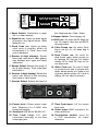
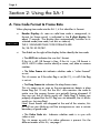
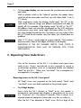
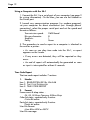
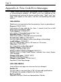
1. Reset Switch: Pushbutton to reset
SA-1 or clear displays
2. Signal In LED: Lights up when signal
is present. Any signal above -30db
lights this LED.
3. Good Code LED: Lights up when
valid code is present; blinks off
momentarily if a “Fatal” time code
error is detected.
4. Reader (8 digit display): Reads
time code, user bits or video phase;
also displays error types and faulty
addresses.
5. Reader Select: Selects the mode of
the 8 digit display: Time code/User
bits/Video ø.
6. Counter (4 digit display): Reads the
frame rate (fr/sec) of the incoming
time code or video signal.
Code
BEEPER
Video
Off
Drop Fr.
Video Code
On
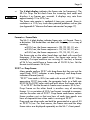
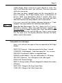
the 4 digit counter: Code / Video.
8. Beeper Switch: Turns beeper off.
9. ASCII LED: On when ASCII flags are
set. On means User bits are ASCII;
off means Hex.
10. Color Frame LED: On when Color
flag is set (bit 11); off when flag is
not set.
12. Drop Frame LED: On solid for
drop frame code; blinks mostly on
for missing DF flag (bit 10); blinks
mostly off for false DF flag; off for
non drop code.
13. Video Code LED: On solid if code
is synchronous and in phase with
video; blinks mostly on if code is out
of phase; blinks mostly off if code is
drifting; off if no video is present.
7. Counter Select: Selects the input of
POWER
RS-232
12VDC
@ 300ma
TIME CODE
LOOP
VIDEO IN
INPUT
Off
75
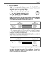
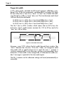
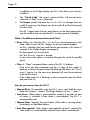
Pin 2: TxD (Signal out)
Pin 3: RxD (Signal in)
Pin 5: SG (Ground)
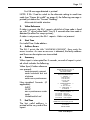
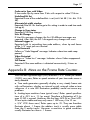
14. Power jack: 2.5mm power input
jack. Requires 6 to 12VDC with
center pin positive.
17. Time Code Input: 1/4” for source
time code.
15. Serial port: DB-9M for RS-232 I/O.
18. Video Input: BNC connector for
video reference.
16. Time Code Loop: 1/4” jack
connected internally to the time
code input jack.
19. Termination switch: turns on
a 75Ω termination for video
reference.