1
2: Hardware Assembly
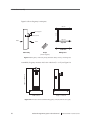
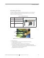
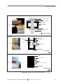
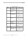
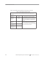
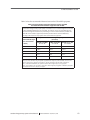
Table 2-4. GPS hardware
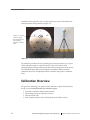
Calibration stand
Manfrotto 3001 BD tripod stand
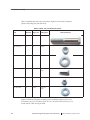
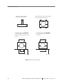
Materials to connect
gantry’s rolling base
to main body
(2) 3/8-16 x 2 1/2 bolts
(2) 3/8-16 hex nuts
(4) 3/8 flat washers
(4) 1/4-20 x 3/4 bolts
(2) 1/4-20 hex nuts
(4) 1/4 flat washers
Assembly requires (1) 9/16 end wrench, (1) 9/16 socket
wrench, (1) 7/16 end wrench, and (1) 7/16 socket wrench,
which are not provided.
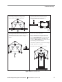
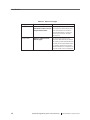
Materials to connect
dome to gantry’s dome
support
(2) 1/4-20 x 3 bolts
(4) 1/4-20 x 2 bolts
(6) 3/8 acorn nuts
(3) pipe clamps
(6) 3/8 flat washers (shims)
Assembly requires (1) 3/8 end wrench and 1 (3/8) socket
wrench, which are not provided.
Assembly Instructions
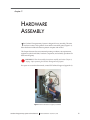
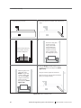
The geodesic dome and gantry are packaged in two separate crates. Bolts, washers,
nuts, and clamps are loosely attached to their intended locations on the equipment.
Caution!: Assembly requires two people because of the GPS size and weight.
Gantry Overview
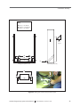
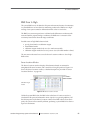
The gantry consists of the rolling base and the main body. Assembly entails securing
the main body to the rolling base. The main body contains a dome support (see Figure
2-3) that is designed to hold the GPS dome. In addition, a motorized control on the
gantry lifts and lowers the dome.
Geodesic Photogrammetry System Technical Manual
S-MAN-200-GPSR-001 • November 22, 2006
35