1
Project
Ember
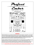
Thank you for purchasing the Project Ember Headphone Amplifier Kit. This kit requires minimal electronics and
soldering knowledge. The layout is easy to follow and setup is a snap! Please make sure to follow the instructions
outlined in this guide and you will be enjoying your amp in no time. First, lets go over the tools and items required
for your build which are as follows:
Required Assembly Tools:
- Soldering iron, 25W minimum – Variable temp soldering station preferred with 1.5 – 2mm wide chisel tip
- .032 diameter 60/40 or 63/37 Tin/Lead solder is recommended. Lead free is difficult to work with and not recommended
- We specifically recommend Kester 331 water soluble flux solder, available on our website for purchase under (Parts – Buy)
- Magnifying glass (recommended but not required)
- Rubber Gloves (recommended but not required)
- 3M Green or Red Scotch Brite (recommended but not required)
- 3/32th Allen Key
- Flush cuts
- 90% Isopropyl alcohol (recommended but not required)
- Paper Towels (recommended but not required)
- Digital Multi Meter (DMM or DVOM)
- Heatgun or Hairdryer (for securing heatsinks)
Before You Start Soldering:
Prep work needs to be done. Wash your hands thoroughly and dry. Put on the recommended rubber gloves and scrub down
the PCB (circuit board) on both the front and back side with 90% isopropyl alcohol to clean any residuals off of the board
from manufacturing. Once the board has been cleaned, set it on a dry paper towel out of the way. Try to use the rubber
gloves during the entire assembly process to keep oils off of the board and solder joints.
Proper soldering is key to a quality final product. If you are new to soldering, here are some basic guidelines to
follow. It would be wise to buy a copper project board and a few cheap resistors or other components to practice
with before starting this project.
Soldering and Solder Joints:
- For best results and maximum conductivity of any component, Wipe each wire lead down using Scotch Bright. Only one
or two passes are required, making sure all of the surface has been cleaned. This removes oxidation or any other build up
on the metal that has accumulated over time. Once cleaned, it is a good idea the further clean the wire leads with 90%+
isopropyl alcohol. Make sure all alcohol has evaporated prior to soldering as alcohol is VERY FLAMMABLE.
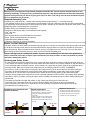
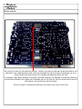
- Do not use to much or to little solder on each joint. See images below to get an idea of what you should be looking for
- The idea is to heat the pad and the component wire lead quickly and efficiently so that solder flows to each equally.
Wetting the tip of your iron with a very small amount of solder will aid in quickly heating up the pad and wire lead.
- Having to heat a component for long periods of time, especially capacitors or LED’s is NOT a good thing. When soldering
capacitors or LED’s, heat them only long enough to ensure a quality joint and let the unit cool down before soldering the
second lead.
- The solder joint should look bright and metallic. A dull or dark gray looking joint is referred to as a
“cold solder joint” Cold solder joints may not pose a problem initially, but can show up later in the amps life.
- After every solder joint, make sure to clean the flux off your soldering iron tip with a wet sponge that should be
provided with your soldering iron kit.
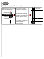
CUTAWAY OF A VIA AND SOLDER PAD
PRIOR TO SOLDERING:
VIA / HOLE
PCB
CUTAWAY
SOLDER
PAD
WIRE
LEAD
PROPER SOLDER JOINT:
IMPROPER SOLDER JOINT:
- Solder is bright and shiny. It is curved
smoothly starting at the edge of the solder
pad until it reaches the lead from the
component
- Solder should fill the via and flow through
the board slightly. It is ok to add solder to
the top side of the board, however it is not
required
- A large blob of solder, often dull in color is
not desired. The solder may not flow into
the via hole and cause a poor connection
or failure later in the amplifiers life.
TOP OF PCB
TOP OF PCB