1
PST-3201/3202 PROGRAMMABLE POWER SUPPLY
PST-3201/3202 PROGRAMMABLE POWER SUPPLY
USER MANUAL
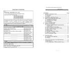
CONTENTS
PAGE
1. PRODUCT INTRODUCTION................................................. 1
1-1. Description……………………………………………… 1
1-2. Feature…………………………………………………... 1
2. TECHNICAL SPECIFICATIONS………………………… 3
3. PRECAUTIONS BEFORE OPERATION…….…………... 5
3-1. Unpacking the Instrument……………….………….…. 5
3-2. Checking the Line Voltage…………………..…………. 5
3-3. Environment……………………………………..……... 6
4. PANEL INTRODUCTION……………………..…………... 7
5. OPERATION METHOD………………………………...…. 11
5-1. Output Voltage/Current Setting…………………..…… 11
5-2. Over Voltage/Current Protection Setting……………... 12
5-3. Voltage/Current Step Setting………………………….. 13
5-4. Information Storing & Recalling Setting……………… 13
5-5. Information Editing & Copying Setting………………. 15
5-6. Auto Operation Mode….………………………………. 16
5-7. Parallel Operation Mode…………………………….…. 17
5-8. Track Operation Mode………………………………… 17
5-9. GPIB/RS-232 Interface Setting………………………… 18
5-10.The Maximum Output Setting……………………….... 19
5-11.Test Lead……………………………………………….. 20
5-12. The Setting of the GPIB and RS232 Interface……….. 20
6. MAINTENANCE………………………..………………….. 21
6-1. Fuse Replacement………………………………………. 21
6-2. Line Voltage Conversion……………………………….. 21
6-3. Adjustment and Calibration…………………………… 22
6-4. Cleaning………………………………………………… 28
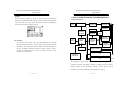
7. THE SYSTEM DIAGRAM AND DESCRIPTION……….. 29
7-1.Block Diagram…………………………………………... 29
7-2.The Operation of the whole circuit……………………... 30
⎯
i ⎯
USER MANUAL
SAFETY TERMS AND SYMBOLS
These terms may appear in this manual or on the product:
WARNING. Warning statements identify condition or
practices that could result in injury or loss of life.
CAUTION. Caution statements identify conditions or
practices that could result in damage to this product or
other property.
The following symbols may appear in this manual or on the product:
DANGER
ATTENTION
Protective
Earth (ground) Frame or Chassis
High Voltage
refer to Manual
Conductor
Terminal
Terminal
⎯
ii ⎯
Terminal