1
CE 3372 Water Systems Design
FALL 2013
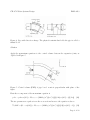
Figure 6: Pipe reducer (transition) diagram.
Solution
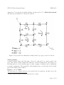
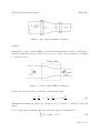
First sketch a control volume (FBD) to identify momentum terms and such, as in Figure 7.
Again we assume the pipes are connected by zero-force joints, so the external force is applied
to only the reducer.
Figure 7: Control volume (FBD) of transition.
Next use the energy equation to find the downstream pressure
p1 V12
p2 V22
V2
+
+ z1 =
+
+ z2 + 0.20 2
γ
2g
γ
2g
2g
(16)
Substituting in numerical values, and solving for p2 we obtain p2 = 4147lb/f t2 (note the
units!).
Now we apply the momentum equation to find the required restraining force
X
Fx = ρQ(V2x − V1x )
(17)
Page 11 of 22