1
IV. PixiePlus Installation cont’d
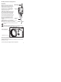
3. Wire Controller
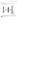
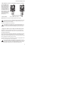
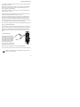
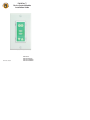
Connect the 3-conductor cable to the captive screw connector on the back of the
PixiePlus. Be sure that the wires match the connections on the cable assembly
block end - the PixiePlus uses crossover wiring.
+6V
BUS
GND
BUS
+6V
GND
Wire landing must match
landing on cable assembly
block at the display device
side (see pg. 4).
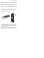
Verify the captive screw connectors are fully open before inserting the wires.
It is possible to physically anchor the wires without making a solid electrical
connection if they are turned the wrong way.
7