1
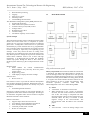
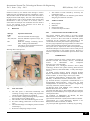
International Journal For Technological Research In Engineering Vol. 1, Issue. 1, Sep – 2013 Real time data processing Tagging Supervisory control Switching orders Load shedding and restoration The distribution management system [DMS] functions are: Operational monitoring Fault isolation and system restoration Variable reactive power(VAR) control Voltage control Distribution power flow Load forecasting Calculation of quality service indices II. ISSN (Online): 2347 - 4718 BLOCK DIAGRAM System concepts The term SCADA usually refers to centralized systems which monitor and control entire sites or complexes of systems spread out over large areas (anything between an industrial plant and a country).Most control actions are performed automatically by remote terminal units or by programmable logic controllers. Host control functions are usually restricted to basic overriding or supervisory level capability [2]. For example, a PLC may control the flow of cooling water through part of an industrial process but the SCADA system may allow operators to change the set points for the flow and enable alarm conditions such as loss of flow and high temperature, to be displayed and recorded. The feedback control loop passes through the RTU or PLC while the SCADA system monitors [3] the overall performance of the loop Hardware used GSM modem for remote communication Electromagnetic relay and relay driver for power supply control Digital energy meter LCD display to display the meter readings Software used Keil u-vision 3.0 keil software is used to provide the software development tools for 8051 based microcontrollers. With the keil tools, we can generate embedded applications for virtually every 8051 derivative. Proload Programmer Software Proload is a software working as user friendly interface for programmer boards from sunrom technologies. Proload gets its name from “Program Loader” term as it takes in compiled HEX file and loads it to the hardware. Features of Proload : Supports major Atmel 89 series devices Auto identify connected hardware and devices Error checking and verification in-built 20 and 40 pin ZIF socket on-board Works on 57600 speed Fig. 1. Operational block diagram of remote data acquisition using wireless SCADA system Theory of operation: In this material, 89S52 microcontroller is interfaced with SIM 300T GSM modem to decode the received message and do the required action. The protocol used for the communication between the two is AT command The microcontroller pulls the SMS received by phone, decode it, recognizes the mobile number and then switches on the relays attached to its port to control the appliances. After successful operation, controller sends back the acknowledgement to the user’s mobile through SMS. A) Sensor A thermistor is used here as a heat sensor When temperature in the vicinity of thermistor increases, the value of the resistance is decreased in case of fire. The voltage is compared with other input and produce voltage at relay and the relay gets activated. When the relay is activated it sends negative voltage to the microcontroller. The microcontroller sends the SMS to the concerned people B) ADC A/D converters convert an analog voltage to the 38