1
KIT COMPONENTS
Identifying the components
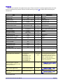
Take an inventory to be sure you have all parts before beginning assembly. The parts list on page 21
lists all the components. This table describes the parts, and includes photos to help you identify them. If an
item is noted as “polarized,” pay extra attention to its orientation when you insert it into the PCB, and be
sure to orient it exactly as directed.
Note: The term "DIP" is an abbreviation for "Dual Inline Package," the style of integrated circuits ("chips")
used in the FCC4.
Static-sensitive components
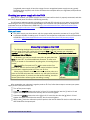
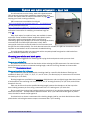
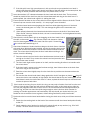
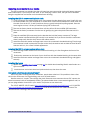
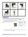
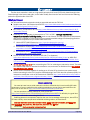
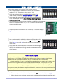
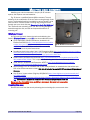
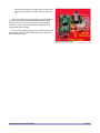
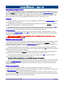
Components that can be damaged by static electricity are shipped in a
piece of black protective antistatic foam. DIP sockets and the Z1 speed
switch also are shipped in this foam to prevent damage to their pins.
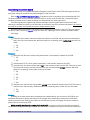
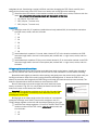
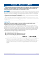
This photo shows the general arrangement of the components in the
foam. Take special care to locate the five three-pin transistors and voltage
regulators. These tiny black components can be hard to see against the
black foam.
See the note on page 26 to make it easier to read the markings on
transistors and voltage regulators.
Fig. 16: Static-sensitive components.
Component
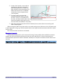
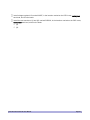
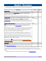
Microprocessor “chip”
Description
Rectangular package
with two rows of pins on
the bottom.
Photo
Notes
This device is the heart of
the FCC4, and can be
destroyed by static
electricity, so keep it in its
black conductive foam
until ready to insert it into
the socket on the PCB.
Before handling it, touch
your hand to a metal
object to discharge any
static electricity.
Polarized. Insert into its
socket with the notched
end (painted orange)
oriented as printed on
the PCB and shown on
page 24.
FCC4 Fast Clock Controller User Manual
Page 16