1
2. In this lecture, we will deal with distributed systems in the broad sense
of the term. In particular, we will discuss systems built using the
“Client/Server” model.
B. In the bulk of this lecture, we will focus on mechanisms available in Java
(and other languages) for allowing client software running on one machine
to interact with server software running on another machine.
C. First, however, we want to spend a little bit of time looking at a type of
UML diagram - the Deployment diagram - that can be used to show how
components of any system are physically deployed.
II. UML Deployment Diagrams
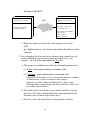
A. The major components of a deployment diagram are nodes - symbols
representing either a processor or some significant piece of hardware that
the system utilizes.
1. The standard symbol for a node is a cube:
2. Nodes representing specialized pieces of hardware can be represented
by specialized symbols, as we shall see shortly.
3. Nodes are connected by associations, representing the flow of
information back and forth between them.
4. We may also explicitly show the network which allows the nodes to
communicate, if they communicate via a general-purpose network
rather than via dedicated hard-wired connections.
5. Note that, in contrast to other diagrams we have drawn, in a
Deployment diagram the symbols represent hardware - not software.
(The software is deployed on one or more processors, depicted by
node symbols.)
2











![Page 1 (12) United States Patent Castaldi et a]. US007118220B2](http://vs1.manualzilla.com/store/data/005861806_1-939e513e2a7d3e1f9213dbaf59950ac6-150x150.png)