1
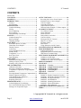
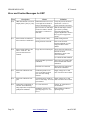
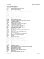
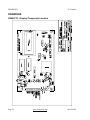
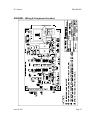
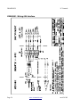
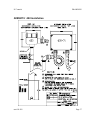
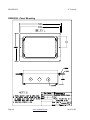
CONTENTS IC Controls CONTENTS um-654-202 CONTENTS............................................................2 654 MENUS............................................................3 INTRODUCTION..................................................6 Features...............................................................6 Specifications......................................................7 INSTALLATION...................................................9 Analyzer Mounting.............................................9 Wiring.................................................................9 Sensor Mounting...............................................10 Sensor Wiring....................................................10 Instrument Shop Test Startup............................11 STARTUP.............................................................13 Analyzer Startup Test........................................13 Start-up Settings................................................13 Changing Settings.............................................13 EASY MENU........................................................14 Remembers Where You Were...........................14 Home Base: Press Sample.................................14 Display Features................................................14 Arrow Keys.......................................................15 AUTO and MANUAL Keys.............................15 Standby Mode...................................................15 Temperature °C or °F........................................16 Real-Time Clock...............................................16 Input Damping..................................................16 EDIT MODE.........................................................17 Editing by Selecting a Setting...........................17 Editing a Numeric Value...................................17 Summary of Key Functions in Edit Mode.........18 ORP CALIBRATION..........................................19 Calibration Procedure........................................19 Selecting a Standard for Calibration.................20 Temperature Compensation for Quinhydrone Standards...........................................................21 Selecting Manual Temperature Compensation..21 Manual Adjustment of Offset............................21 Output Hold During Calibration.......................22 Electrode Maintenance......................................22 Replacing Electrodes.........................................22 ERROR MESSAGES...........................................23 Acknowledging an Error Message....................23 Error and Caution Messages for ORP...............24 Messages for Temperature Input.......................25 OUTPUT SIGNALS.............................................26 Reversing the 4 mA to 20 mA Output...............26 Simulated 4 mA to 20 mA Output.....................26 Units for Outputs...............................................26 Output Specifications........................................26 Output Characterization....................................27 Characterization Example: Tri-linear output....27 ALARM FUNCTIONS........................................30 Use of Relay Contacts.......................................30 Alarm Indication...............................................30 Alarm Override.................................................31 Delayed Relay Activation..................................31 Units for Alarms................................................31 Wiring and NO/NC Contacts............................31 High or Low Alarm...........................................32 Deviation Alarm................................................32 Fault Alarm.......................................................32 Using Alarms for On/Off Control.....................33 CONFIGURATION OF PROGRAM.................34 TROUBLESHOOTING.......................................36 Isolating the Problem.........................................36 Equipment Problem Troubleshooting................37 ORP Sensor Troubleshooting............................38 ELECTRONIC HARDWARE ALIGNMENT..39 Calibration of ORP Input..................................39 Calibration of Temperature Input......................41 Calibration of 4 mA to 20 mA Outputs.............41 DISPLAY PROMPTS..........................................43 GLOSSARY..........................................................45 Appendix A — Security.......................................46 Appendix B — Output Characterization...........49 Appendix C — Default Settings..........................50 Appendix D — Serial Output..............................51 Appendix E — Parts List.....................................53 DRAWINGS..........................................................54 D5980176: Display Component Location........54 D5900081: Wiring & Component Location.....55 D5900080: Wiring 600 Interface.....................56 D4850015: 600 Installation..............................57 D4830022: Mounting Dimensions...................58 D4950053: Pipe/wall Mounting.......................59 D4950054: Panel Mounting.............................60 INDUSTRIAL PRODUCTS WARRANTY.......61 INDEX...................................................................62 Copyright 2007 IC Controls Ltd. All rights reserved. Page 2 www.iccontrols.com um-654-202