1
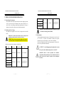
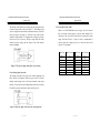
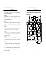
PSH SERIES PROGRAMMABLE POWER SUPPLY USER MANUAL 20mV, if it is smaller than 36V, the minimum adjustable step of the rotation knob is 10mV. 5-3.Over Voltage /Current Protection Setting --Over Voltage Protection Setting: Set to OVP SET window by pressing [MENU], modify the OVP setting value with [F/C] key to input integral or dismal number, then press [ENTER]. --OVP Status Clear Up: When the output voltage exceeds the setting voltage, the instrument will stop output and get into OVP mode by displaying “OVP Error. Press “LOCAL” to reset” messages on the panel. Now press [LOCAL] to clear OVP status, back to previous status. --Over Current Protecti on Setting: Set to OCP SET window by pressing [MENU], then switch OCP to ON or OFF with the knob and press [ENTER]. When the OCP is on, the output current equals or exceeds the setting current, the instrument will stop output and get into OCP mode by displaying “OCP Error. Press “LOCAL” to reset” messages on the panel, Now press [LOCAL] to clear OCP status, back to previous status. 5-4. Display Contrast Setting: Set to Contrast Setting window by pressing [MENU], modify the Contrast setting value with knob, then press [ENTER]. PSH SERIES PROGRAMMABLE POWER SUPPLY USER MANUAL using the wheel knob to modify the value and press [ENTER] to complete the setting. Note: The system will detect the interface used at present automatically, and switch the detected interface over the setting interface of GPIB or RS-232. Example: 1) If want to set the GPIB address value to 08: Set to interface window by pressing [MENU], and adjust the address value to 08 with the wheel knob and p ress [ENTER] to complete the setting. 2) If want to set the RS-232 Baud Rate to 9600: Set to interface window by pressing [MENU], and adjust the Baud Rate value to 9600 with the wheel knob and press [ENTER] to complete the setting. For further details, please refer to the programmer manual of PST/PSS/PSH series programmable power supply. 5-7. Remote Error Sensing A normal power supply can perform its best load regulation, line regulation, low output impedance, and low output ripple and noise, as well as the rapidly transient recovery response. Please refer to figure 5-2. If there is any test lead connected between load and output terminal, the best characters of power supply can not be shown up on the load terminal. 5-5. Buzzer Setting Set to Buzzer Set window by pressing [MENU], switch Buzzer to ON or OFF with the knob, then press [ENTER]. 5-6. GPIB/RS232 Interface Setting Set to Interface window by pressing [MENU]. If the GPIB is displayed, the Address value window will be appeared, if the RS-232 is displayed, the Baud Rate window will be appeared, then 16 Figure 5-2 The power supply with local error sensing 17