1
5
5,237,652
indicates that the oven will remain on
SwTemp
TimeZero
AtTemp
Microwaves
Warming
TimerRunning
until a predetermined temperature is
reached
This input is true in temperature mode,
tively, indicating a logical OR operation. Line segment
132 includes segment 136 that indicates the beginning of
a ladder logic graph. The symbol “L” in output symbol
130 re?ects the latch indicator “L” appearing at the end
of program line 12. The latch indicator speci?es that the
Microwaves output will be latched into the true state by
false in timer mode
This input has the value true when the
mechanical timer has counted down to
zero, and otherwise has the value false
This input has the value true when the
temperature has reached a preselected
level, and otherwise has the value false
l0 the PLC whenever the conditions shown in FIG. 60 are
The oven is on when this output is true,
satis?ed. Thus an operator of the microwave oven is
and off when this output is false
As described below, this internal variable
represents an "intemal relay" that is not
associated with any IO point. Its
signi?cance is further described below
This internal variable represents a second
internal relay
6
spond to the internal variables TimerRunning and
Warming, respectively. These input symbols are con
nected in parallel by line segments 132 and 134, respec
-continued
only required to momentarily depress the Start switch
15
in order to turn the oven on. In a preferred embodiment
of the invention, each output variable can have one of
four modes. These modes are normal (N), one-shot (O),
toggle (T), and latch (L). The N mode is the default,
and causes the output variable to be on when its input is
on, and off when its input is off. Latch mode causes the
In the present system, the fact that the Warming and
output variable to remain on even after its input is off.
Timer Running are internal variables is indicated by the 20 For an output variable that has been latched, the vari
numbers of the IO points (119 and 118) associated with
these variables. An internal variable can be both an
able is turned off using the R symbol. Finally, one-shot
mode indicates that when its input is on, the output
input variable and an output variable. For example, in
variable remains on for one complete scan, and then is
line 10, internal variable Warming is an output variable,
while in lines 12 and 13, internal variable Warming is an 25 turned off.
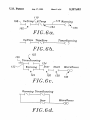
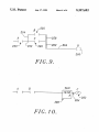
As indicated in FIG. 6a‘, the microwave output will
input variable.
be reset (R) whenever the door is open, or whenever
Line 10 of the PLC program set forth above states
the oven reaches the preset temperature in temperature
that when input SwTemp is true AND input AtTemp is
mode or the end of a preset interval in timer mode.
false, then internal variable Warming is true. When this
ladder logic command is selected in block 86 of FIG. 5, 30 Comparing program lines 1043 with FIGS. 6a~6d
readily indicates the improvement in program writing
display function 88 determines and produces the ladder
and debugging that is made possible by the present
logic graph shown in FIG. 6a, in which the ladder logic
invention.
command has been translated into an equivalent ladder
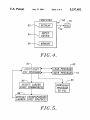
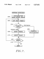
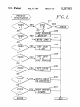
FIGS. 7 and 8 set forth a ?ow chart for a preferred
logic graph. The ladder logic graph comprises input
symbols 102 and 104, output symbol 106, and line seg 35 embodiment of the display function. The operation of
these flow charts will be illustrated by program line 12
ments 108, 110, and 112. Each input symbol comprises a
above, and the corresponding ladder logic graph shown
pair of spaced vertical bars, the name of the correspond
in FIG. 6c. The display function of FIG. 7 begins with
ing input variable above the bars, and the horizontal
an initialization step in block 200. Preferably, the dis
lines to either side of the vertical bars. Output symbol
106 is similar, except that it includes parentheses rather 40 play area on which the ladder logic graph will be drawn
than vertical bars. Input symbol 104 includes a back
is divided into a two-dimensional array of grid elements,
slash that re?ects the logical NOT symbol appearing
with each grid element being large enough to display an
input or output symbol. On a conventional 80X 25 com
with this in front of the AtTemp variable in program
line 10. Line segment 108 simply indicates the beginning
puter monitor, a suitable size for each grid element is
of the ladder logic graph, line segment 110 indicates a 45 eight characters wide and two characters high.
logical AND operation corresponding to the period in
Block 200 initializes a current grid pointer, preferably
program line 10, and line segment 112 connects the
to a grid element at the left center of the drawing area.
input symbols and their associated logic with output
Block 200 then proceeds to draw the entry point for the
symbol 106.
ladder logic graph, the entry point being shown by
For many if not most PLC programmers, the graphi 50 reference number 136 in FIG. 6c. Each time that a given
cal display shown in FIG. 6a can be more readily com
graph element is drawn, the grid pointer is updated in a
prehended than the textual command shown in program
corresponding manner. Thus, in the case of entry point
line 10 above. However, the programming system of the
136, the grid pointer would be incremented to specify
present invention does not require the user to painstak
that the next portion of the ladder logic graph will be in
ingly create a ladder logic graph on the computer 55 the middle row, second column, of the grid array.
screen. Instead, the invention requires the user to per
The program diagrammed in FIG. 7 then proceeds in
form the far simpler task of typing in an alphanumeric
block 202 to obtain the next token from the alphanu
command, and the corresponding ladder logic graph
meric ladder logic command. A “token" is a unit of the
may then be created automatically.
ladder logic command. Thus for program line 12, the
In a similar manner, FIGS. 6b, 6c, and 6d illustrate the 60 tokens are the variable names TimerRunning, Warming,
ladder logic graphs created by display function 88 for
PLC program lines 11-13, respectively. FIG. 6b illus
trates the setting of the internal variable TimerRunning.
Door, Start, and Microwaves, and the punctuation sym
bols< , comma, period, backslash, and>. Block 204
examines the next token, to determine whether it is a
FIG. 6c shows how the microwave oven is turned on,
variable name or a punctuation symbol. In program line
while FIG. 6d shows how the microwave oven is 65 12,-the ?rst token is the punctuation symbol<, so that
turned off. Examining FIG. 6c in detail, this ladder logic
program control ?ows to block 206 that is further dia
graph includes input symbols 122, 124, 126, and 128, and
grammed in FIG. 8. For the token “<”, block 232 will
output symbol 130. Input symbols 122 and 124 corre
cause all flags to be reset to their default values, since