1
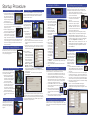
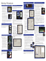
12. Checking the toolbar position
After the toolbar is loaded, check the toolbar position:
1. In BoardMaster, select the #1 tool
from the Selected Tool drop-down box
(figure 18).
2. As tool is selected, monitor the drill
head and make sure that the tool is
cleanly lifted from the tool bar without
scraping or catching, and that the tool
does not fall from the collet after lifting.
3. Repeat steps 1 and 2 for all ten tools.
Monitor each tool as it’s replaced,
18. Selecting tool #1
making sure that it is replaced firmly
into the toolbar, at the same level as the other tools, upright, and
smoothly, without catching or scraping against any part of the
ProtoMat.
Any tool position that exhibits scraping, catching, dropping, or other
signs of misalignment must be adjusted (see Adjusting the toolbar
position).
13. Adjusting the toolbar position
Adjust the toolbar position only if indicated by a misaligned tool or other
calibration error. Adjusting the tool position is sometimes necessary,
due to normal operating fluctuations such as
movement, temperature changes, and humidity
changes.
There are two different procedures, depending
on if a camera is installed. Refer to the Users
Manual for more detailed explanations.
19. The Measure Insert
in position #1
If there is a camera installed:
1. Set the Camera Offset (see Set/Calibrate camera offset).
2. Turn the ProtoMat on, send the machine head to the “Pause”
position, and remove all tools from the tool magazine.
3. Place the brass Measure Insert into tool position #1 (figure 19)
and close the hood.
20. Choosing tool #1
4. In BoardMaster, select Configuration >> Toolbox..., click
on tool position #1 in the Tool
Box list (figure 20), and click
the “Service” button. When
prompted for the Service
password, enter BMASTER.
5. Click the “Check:(1)” button,
use the Z keys in the main
interface to focus the image
and the XY keys to center
the crosshairs directly over
the tool position (figure 21).
Click “Accept” button when
21. The Measure Insert in the camera.
finished.
6. Repeat steps 3 through 5 for the remaining tool positions.
7. Close the Tool Box dialogue by clicking “OK” and send the
machine head to the “Pause” position.
8. Reinstall the tools in the tool magazine and restart BoardMaster.
If there is no camera installed:
1. Turn the ProtoMat on and make sure that there is a tool in every
slot of the tool magazine, and that there are no tools in the
ProtoMat’s collet.
2. In BoardMaster, select Configuration >> Heads..., choose
Camera under the Head drop-down box, and set both offset
values to 0, and click “OK”.
3. In BoardMaster, select Configuration >> Toolbox...,
click on tool position #1, and click the “Service” button. When
prompted for the Service password, enter BMASTER.
4. Under “Main/Aux. Clamp”, select “Open”, click on tool position
#1 in the Tool Box list, and click the “Check” button.
5. In the main BoardMaster interface, enter 35 in the step-size
window for the Z axis and click the Z axis down button. If a
dialogue box opens asking to set up a movement border, this
is normal. Click “Yes”. The machine head will lower and if
the head is properly aligned, the machine head will drop to the
bottom without sticking, or dislodging the tool. Click the Z axis
up button and the head should rise back to the original position
without sticking or dislodging the tool.
6. If the head is not properly adjusted, use 0.1 mm increments on
the manual X/Y controls to adjust the head until step 5 can be
completed smoothly without the tool or the head sticking.
7. Click the “Accept” button and repeat steps 3 through 6 for each
tool position on the tool magazine.
8. Close the tool box dialogue by clicking “OK” and restart
BoardMaster.
Thank You!
Thank you for purchasing an LPKF ProtoMat Circuit Board Plotter. ProtoMat circuit board plotters are key elements of any in-house
production, from precision one-off prototyping to short-run production.
Ensure years of solid performance by following the setup and installation instructions in this Quick-Start Guide carefully, and review the more
extensive documentation supplied with the ProtoMat when referred.
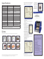
ProtoMat Anatomy
Hood
Milling motor
22. Measuring the actual hole diameter
A: click here first.
B: click here second.
C: read measured value.
Machining head
Vacuum hose
Fiducial recognition camera
Working depth limiter
Tool position #1
Vacuum table
Workpiece
14. Set/Calibrate camera offset
The camera offset must be adjusted and calibrated the first time the
ProtoMat is used, any time the camera is replaced, or any time the
offset is in question.
1. Set up a piece of scrap board material in the working area, switch
on the ProtoMat, and use BoardMaster to manually select a 1.5
mm drill and drill a single hole in the scrap material. Do not move
the machine head after drilling.
2. In BoardMaster, select Configuration >> Heads..., select
the Camera and click “Origin”, then “OK”.
3. In the BoardMaster menu, select Go to >> Camera >>
Head and use the manual XY controls to move the head such
that the crosshairs are as directly centered on the visible hole as
possible (For better precision, decrease the step width to 0.005
mm). Use the Z controls to bring the image into as clear a focus
as possible and press the “Set Focus” button.
4. When the crosshairs are as centered as possible, in BoardMaster,
select Configuration >> Heads..., click the “Head” button,
and then click “OK” to lock the new offset.
5. In the Camera Image window, click “Settings” to open the Setting
window. Adjust
the Brightness
and Contrast
to create a
strong contrast
between the
C
edges of the
hole and the
background of
the work piece
(figure 22).
A
B
Ideally, the hole
should be black
and the work
piece light gray.
Spring head and adjustment
Tool magazine
Case
Tool position #10
Power switch and
fuseblock located
behind side cover.
For clear access,
remove side cover
(8 screws).
Setting options:
Fuseblock settings
Machine table
(under vacuum table)
110/115 V
Shipping Checklist
Verify the following items are included with the S62 or S100:
•
•
•
•
•
•
•
•
•
•
Circuit board plotter and pre-assembled hood
Data cable (9-pin PC to RJ45 ProtoMat cable)
Power cable (standard power supply cable)
ProtoMat user manual (includes BoardMaster operations)
CircuitCAM user manual
CD-ROM with BoardMaster and CircuitCAM software
CD-ROM with Configuration Files
CD-ROM tutorial
Base material (connected to machine base plate)
Accessory set (tools, drills, fuses, and depth limiter foot)
Other References
Please review all documentation, including printed material and the CD-ROM tutorial, for more details.
Online support: http://www.lpkfusa.com/ and http://www.protomat.com/ and support@lpkfusa.com
220/240 V