1
Galaxy Raid GHDX3-1840R/S-24F8D Installation and Hardware Reference Manual
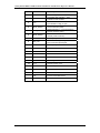
Pin
Pin Name
Pin Description
Transmitter ground
1
VEET
2
TFAULT
3
TDIS
4
MOD_DEF(2)
5
MOD_DEF(1)
6
MOD_DEF(0)
7
No Connect
Internal pullup 30KΏ to Vcc
8
RX_LOS
Indicates loss of signal; High indicates
loss of received optical signal
9
No Connect
Internal pullup 30KΏ to Vcc
10
VEER
Receiver Ground
11
VEER
Receiver Ground
12
RD-
Inverse Received DATA Out
13
RD+
Received Data Out
14
VEER
Receiver ground
15
VCCR
Receiver power +3.3V
16
VCCT
Transmitter power +3.3V
17
VEET
Transmitter ground
18
TD+
Transmitter DATA In
19
TD-
Inverse Transmitter Data In
20
VEET
Transmitter Ground
Transmitter fault indication – High
indicates a fault condition
Transmitter Disable – Module electrical
input disables on high or open
Module definition 2 – Two wire serial ID
interface data line (SDA)
Module definition 1 – Two wire serial ID
interface clock line (SCL)
Module definition 0 - Grounded in module
(module present indicator)
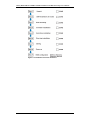
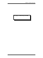
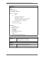
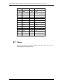
Table B-1: SFP Port Pinout Definitions
B-2