1
UT-2 v3.1 EN Rev.C.doc
2007-10-18
Notes
GENERAL DESCRIPTION
The UT-2 operates as an electrical converter between RS232 and RS485 communication
interfaces, it can be used for programming of single PR series access controller or for
management of a networked access system RACS (Roger Access Control System). The
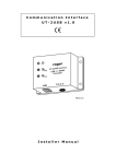
UT-2 is delivered in black plastic case and offers three signalization LEDs. The UT-2 is
equipped with 1.5m cable terminated with DB-9 connector which is dedicated for
connection to PC, connection with an access system or individual controller is carried out
through screw terminals.
RS485 TRANSMISSION CONTROL
Normally, the UT-2 operates in receive mode, it means that all data received by UT-2
through RS485 lines is shifted immediately to RS232 serial interface. With the first byte of
data received from RS232, the UT-2 immediately switches the RS485 interface (lines A
and B) into transmit mode. The RS485 remains in that mode as long as data is received
through RS232. The RS485 returns automatically to receive mode after 1.5 ms time from
the moment when last bit of data has been received from RS232.
Note: The method which is used for RS485 transmission control is developed for PR series
of access controllers from Roger. Optionally, the UT-2 can be used in other application
which require RS232-RS485 conversion but in such cases installer must perform adequate
tests to ensure that UT-2 will operate satisfactory in given applications.
No.
1.
RTS AND CTS LINES
Generally, the RTS and CTS lines are dedicated to improve communication between
managing computer and access systems which are equipped with CPR32-SE. The use of
RTS and CTS lines in such systems is not obligatory and may be omitted. When used both
lines must be connected to adequate input and output of CPR32-SE network controller.
2.
Note: The use of RTS and CTS lines requires PR Master v4.3 and CPR32-SE v30 or
higher.
LED INDICATIONS
The UT-2 is equipped with three LEDs which functions are characterized below.
3.
LED
Symbol
Color
Function
POWER
Amber
Power supply
TXD
Green
Data send to RS485 comm. Bus
RXD
Red
Data received from RS485 comm. bus
4.
INSTALLATION
Locate interface close to PC computer (max. distance is 15m) in a dry area, all electrical
connections must be made with power supply off. UT-2 requires 12VDC supply and up to
150mA current. Interface can be supplied from any device installed in access system
which offer DC supply output or from separate supply source. Note, that supply minus of
UT-2 must have the same potential, in respect to earth, as other devices connected to the
same RS485 bus. This condition can be assured by means of additional wire which will
connect all supply minuses in a system or by adequate grounding arrangements. The UT-2
can be connected to RS485 communication bus in any, arbitrary selected location. The
topology of RS485 communication bus in RACS system is free and may incorporate tree,
-2-
5.
Fault description
Date of repair
(filled out by the customer)
(filled out by the
service)