1
SYSTEM SET-UP
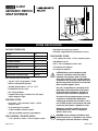
MACHINE PLACEMENT
Power and Safety Wiring Checks
Place the Automatic Stretch Wrap Machine close to
an area where you will be wrapping your pallet loads.
Make sure that there is sufficient room to load/unload
the machine and that you do not stretch the wiring
cable. Remember, you will need to provide electrical
service to a 120 VAC, 15-AMP outlet.
1. Using a voltage meter, check the AC voltage
coming to the system to insure proper voltage is
present.
Floor weight bearing tolerance
The floor must be able to bear the weight of the
machine, the weight of the maximum load, plus a safety
factor. The floor must also be able to tolerate the stress
of the machine’s operation. If the fork trucks will operate
on the same weight bearing area, add the weight
of the trucks to the weight bearing stress tolerance
requirements.
WARNING! The Stretch Wrap Machine must be
anchored securely to the floor, using the type
of anchor recommended for your floor.
MACHINE SET-UP
1. Place skidded machine close to the designated
wrap area. Remove all shipping fasteners holding
the machine to the pallet. The machine may be
crated with the tower tilted down with the motor
cover front carriage roller removed for shipping
purpose.
2. Place forks of the forklift through the tubes provided
at the rear base of the module, remove the machine
from these skids, and place it at the designated
wrap area.
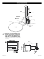
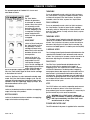
3. If the optional ramp (H-2958) is purchased:
Select a ramp position as illustrated below. The
ramp can be positioned anywhere in a 180° rotation
around the front of the turntable. There should be a
¼" gap between the turntable and the ramp. The
ramp should be fully supported by the floor. Both the
ramp and the machine should be lagged to the floor.
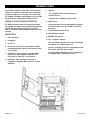
2. Make sure the "E-STOP" button is pressed in. Turn the
disconnect switch to ON position.
3. Pull the "E-STOP" button on the operator panel out.
Power should be applied to the frequency drives,
operating touch-panel, photoelectric sensors,
switches, and LED’s.
4. Press the "E-STOP" button. Make sure all machine
power is completely removed when the "E-STOP" is
depressed. Pull the "E-STOP" button out to resume.
5. Open the film carriage door. Make sure all machine
power is completely removed when the carriage
door is open. Close the film carriage door to resume.
6. Open the electrical control box. Make sure all
machine power is completely removed when the
electrical control box is open. Close the electrical
control box to resume.
7. Trip the carriage foot security bar. Make sure all
machine power is completely removed when the
carriage foot security bar is tripped. Clear the bar to
resume.
PLC's Input Module Checks
1. Open the electrical control box, and insert the key
latch onto the safety door switch.
2. Depress push buttons and activate selector
switches on the operator panel, check for each
corresponding input lights on the front face of PLC.
3. Block the "Product Height Detection" photoelectric
sensor (located on the film carriage), check for
corresponding input light on the front face of PLC.
4. Trigger magnetic proximity and limit switch sensors,
check each corresponding input lights on the front
face of the PLC.
WARNING! Do NOT remove or modify the fixed
upper and lower limit switch stops.
¼" Gap
5. Remove the key latch, and close the electrical
control box to resume.
180˚
PAGE 3 OF 17
0411 IH-2957