1
3D Pipe Junction Using Hexa Meshing
Prerequisites
This tutorial assumes that you are familiar with the menu structure in ANSYS ICEM
CFD and that you have read about this functionality. Some of the steps in setup and the
procedure will not be shown explicitly.
For details about hexa mesh generation, refer to the Chapter, Hexa, in ANSYS ICEM
CFD user manual.
Conventions
Some of the basic conventions used in this tutorial are:
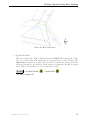
• The icon to the left of the text (here, Blocking) suggests that you have to select the
option from the display tree.
Blocking
• The arrow mark with the text LMB in the box the suggests that you have to click
the left-mouse button to enable or disable an option (here, Vertices).
LMB
−→ Vertices
• The arrow mark with the text RMB in the box the suggests that you have to click
the right-mouse button to enable or disable an option (here, Numbers).
RMB
−→ Numbers
For detailed information about GUI and text conventions, refer to the document, Getting
Started with ANSYS ICEM CFD.
Preparation
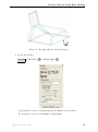
1. Download the ICEM hexa 3dpipe FILES.zip file from the ANSYS Customer Portal. It contains the necessary input geometry file (hexa 3dpipe.tin).
2. Start ANSYS ICEM CFD and open the geometry (hexa 3dpipe.tin).
File > Geometry > Open Geometry...
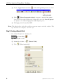
Step 1: Creating Parts
In the first two tutorials, the parts were already defined. For this and the remaining
tutorials, the initial geometry is contained in a single part. You will put the geometry
into different parts to define different boundary regions.
2
c ANSYS, Inc. February 11, 2010