1
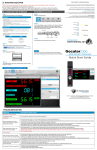
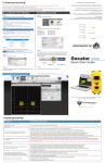
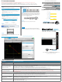
GOCATOR OVERVIEW
Refer to the Gocator user manual for more information about the
sensor, including Clearance Distance (CD), Measurement Range
(MR) and Field of View (FOV).
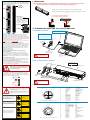
Mounting
Holes
M5X0.8 10
1. MOUNTING
NOTE: Mounting the Gocator is recommended before applying power. Also, ensure that a proper earth
ground is established and that a heat sink has been fitted before applying power.
Camera
Mount the sensor using six M5 x 0.8 screws of suitable length.
The recommended thread engagement into the housing is 8 - 10 mm.
Do not install near surfaces that might
create unanticipated laser reflections.
LED Indicators
When starting Gocator,
Power indicator and
Laser indicator (if safety is
enabled) should be on. If
not, refer to Troubleshooting
table or user manual.
Laser
Emitter
Power/LAN
2. CONNECTING GOCATOR TO A HOST COMPUTER
I/O
Connector
Camera
Standalone System
GROUNDING GOCATOR
Gocator housings should be grounded to the earth and the
grounding shield of the Gocator I/O cordsets. Gocator
sensors have been designed to provide adequate grounding
through the use of M5 x 0.8 screws. Always check grounding
with a multi-meter to ensure electrical continuity between the
mounting frame and the Gocator connectors.
The frame or electrical cabinet that the Gocator is mounted to
must be connected to earth ground.
Power: 24-48VDC @ 13W
Laser Safety: +24-48VDC to enable
Wire rich I/O
as required by application
ex. Serial / Analog / Trigger Input,
Encoder / Photocell / etc.
GOCATOR*
GOCATOR I/O
CORDSET
GROUNDING CORDSET (RECOMMENDED)
To minimize interference with other equipment, the Power &
Ethernet or the Power & Ethernet to Master cordset (depending on cordset used in system) can be grounded by terminating the cordset shield before the split. The most effective
grounding method is to use a 360-degree clamp. See User
Manual for instructions.
ELECTRICAL SAFETY
Minimize voltage potential between system ground
and sensor ground
Care should be taken to minimize the voltage potential
between system ground (ground reference for I/O signals)
and sensor ground. Use shielded cables with shield grounded
at both ends. Sensor housing should be connected to earth
ground.
Use a suitable power supply
The +24-48V power supply used with Gocator 2880 sensors
should be an isolated supply with inrush current protection.
Use care when handling powered devices
Wires connecting to the sensor should not be handled while
the sensor is powered. Doing so may cause electrical shock to
the user or damage to the equipment.
GOCATOR POWER and
ETHERNET CORDSET
Always power down sensor
before removing cables
from the sensor
USER PC
(can be disconnected after setup)
*Not to scale
GOCATOR 2880 SERIES
Dual / Multi-Sensor System
POWER, LASER SAFETY,
TRIGGER INPUTS, ENCODER
MAIN GOCATOR*
BUDDY GOCATOR*
MASTER 400/800/1200/2400
Failure to adhere to the guidelines described
in this section may result in electrical shock
or equipment damage.
The full laser safety details including precautions,
responsibilities and requirements are stated in the Gocator
User Manual. Use of controls or adjustments or performing
procedures other than those specified in the User Manual may
result in hazardous radiation exposure.
Laser
GOCATOR I/O
CORDSET
GOCATOR
POWER AND
ETHERNET CORDSET
Sensor
GIGABIT ETHERNET SWITCH
Leave protective caps on any
connectors that are not used.
Laser
*Not to scale
Connector Pin Details
WARNING: DO NOT LOOK DIRECTLY
INTO THE LASER BEAM
The light emitted from these devices has been set in accordance
with IEC60825. However, staring into the beam, whether directly
or indirectly, must be avoided. IEC60825 classifies laser products
into three different categories depending on light emitted,
wavelength and eye safety.
This product is designated for use solely as a component and as
such it does not fully comply with the standards relating to laser
products specified in U.S. FDA CFR Title 21 part 1040 and
IEC 60825-1.
Gocator Power/LAN (to standalone and to Master)
10
12
5
3
11
9
6
Class 2M: LASER RADIATION
DO NOT STARE INTO THE BEAM
OR VIEW DIRECTLY WITH
OPTICAL INSTRUMENTS CLASS
2M LASER PRODUCT
LASER RADIATION
AVOID EXPOSURE TO THE BEAM
CLASS 3B LASER PRODUCT
PEAK POWER:
EMITTED WAVELENGTH:
IEC 60825-1:2007
4
8
13
130 mW
660 nm
This product is designated for use solely as a
component and as such it does not fully comply
with the standards relating to laser products
specified in U.S. FDA CFR Title 21 part 1040
and IEC 60825-1
1
2
7
14
View: Looking into the connector on the sensor.
Gocator I/O
LASER RADIATION
AVOID EXPOSURE TO THE BEAM
CLASS 3B LASER PRODUCT
Class 3R: LASER RADIATION
AVOID DIRECT EYE EXPOSURE
CLASS 3R LASER PRODUCT
PEAK POWER:
EMITTED WAVELENGTH:
IEC 60825-1:2007
450 mW
808 nm
This product is designated for use solely as a
component and as such it does not fully comply
with the standards relating to laser products
specified in U.S. FDA CFR Title 21 part 1040
and IEC 60825-1
19
16
LASER RADIATION
AVOID EXPOSURE TO THE BEAM
CLASS 3B LASER PRODUCT
PEAK POWER:
EMITTED WAVELENGTH:
IEC 60825-1:2007
Class 3B: LASER RADIATION
AVOID EXPOSURE TO BEAM
CLASS 3B LASER PRODUCT
130 mW
660 nm
This product is designated for use solely as a
component and as such it does not fully comply
with the standards relating to laser products
specified in U.S. FDA CFR Title 21 part 1040
and IEC 60825-1
18
17
2
15
4
5
9
14
6
INVISIBLE LASER RADIATION
AVOID EXPOSURE TO THE BEAM
CLASS 3B LASER PRODUCT
PEAK POWER:
EMITTED WAVELENGTH:
IEC 60825-1:2007
450 mW
808 nm
This product is designated for use solely as a
component and as such it does not fully comply
with the standards relating to laser products
specified in U.S. FDA CFR Title 21 part 1040
and IEC 60825-1
1
3
10
12
8
7
11
13
View: Looking into the connector on the sensor.
Pin
1
1
2
2
3
4
5
6
7
8
9
10
11
12
13
14
Function
GND_24-48V
GND_24-48V
DC_24-48V
DC_24-48V
SafetySafety+
Sync+
SyncEthernet MX1+
Ethernet MX1Ethernet MX2+
Ethernet MX2Ethernet MX3Ethernet MX3+
Ethernet MX4+
Ethernet MX4-
Conductor Color
White/Orange & Black
Orange/Black
White/Green & Black
Green/Black
White/Blue & Black
Blue/Black
White/Brown & Black
Brown/Black
White/Orange
Orange
White/Green
Green
White/Blue
Blue
White/Brown
Brown
Pin
1
2
3
4
5
6
7
8
9
10
11
12
13
14
15
16
17
18
19
Function
Trigger_in+
Trigger_inOut_1+ (Digital Output 0)
Out_1- (Digital Output 0)
Out_2+ (Digital Output 1)
Out_2- (Digital Output 1)
Encoder_A+
Encoder_AEncoder_B+
Encoder_BEncoder_Z+
Encoder_ZSerial_out+
Serial_outReserved
Reserved
Analog_out+
Analog_outReserved
Conductor Color
Grey
Pink
Red
Blue
Tan
Orange
White/Brown & Black
Brown / Black
Black
Violet
White/Green & Black
Green / Black
White
Brown
Blue / Black
White / Blue & Black
Green
Yellow & Maroon/White
Maroon