1
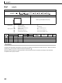
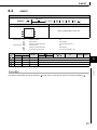
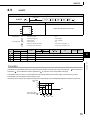
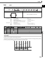
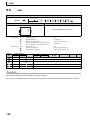
S.IPD
Set
Data
Block
diagram
9
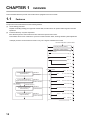
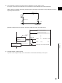
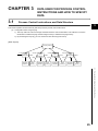
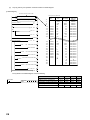
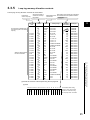
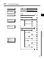
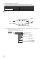
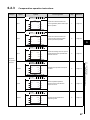
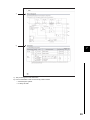
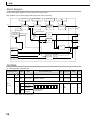
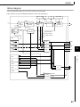
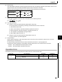
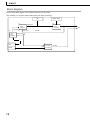
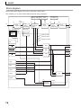
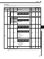
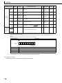
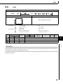
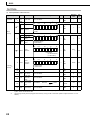
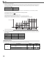
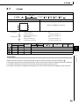
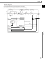
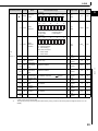
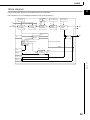
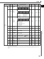
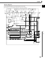
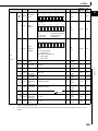
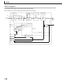
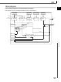
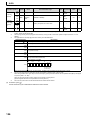
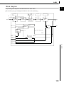
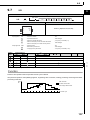
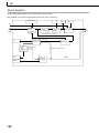
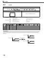
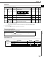
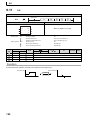
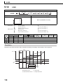
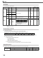
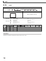
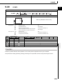
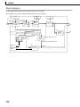
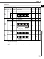
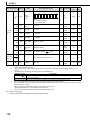
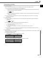
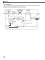
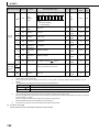
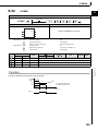
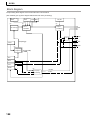
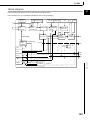
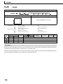
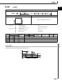
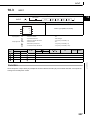
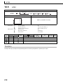
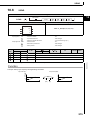
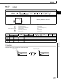
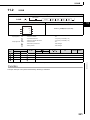
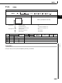
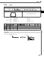
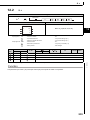
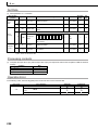
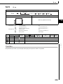
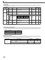
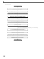
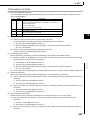
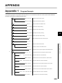
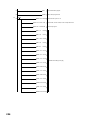
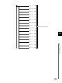
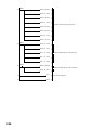
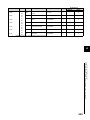
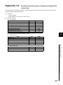
The processing block diagram of the S.IPD instruction is shown below.
(The numerals (1) to (7) in the diagram indicate the order of the processing.)
RL, RH
DV
2
GW,
GG
P, I, D, CT, MTD
DVL, DVLS
E1
(1)
(2)
SV setting
processing
(When used)
Gain Kp
operation
processing
Tracking
processing
Deviation
check
IPD operation
BW
4
Control cycle
judgment
(6)
3
(5)
When in control
cycle
(7)
CT
(4)
(3)
E2
AND
BB1
RUN(SPA=0)
Loop
stop
judgment
STOP(SPA=1)
6
When not in control cycle
BW=0
7
(6)
SPA
MODE
4
BW=0
MAN
Loop stop
processing
OFF
8
ERRI∩DVLI
DVLA
9.5
S.IPD
123