1
ASSEMBLY
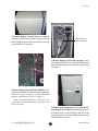
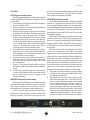
mounting holes
5
6
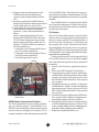
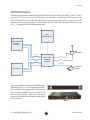
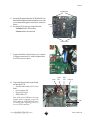
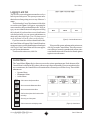
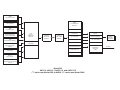
Mount the Peripheral Interface PCB (M404810) to
the standoffs within the Peripheral Interface case with
screws inserted through its corner holes, oriented as
shown.
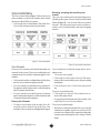
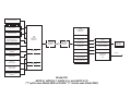
Set jumper JP1 for the type of data link used:
• Installed for RS-485 landline
• Removed for radio data link
chassis
rear
chassis bottom
mounting holes
7
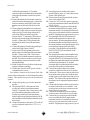
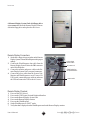
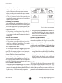
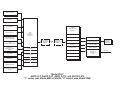
Connect the ribbon cable from the case’s external
COM port connector to J11 on the Peripheral Interface PCB, and screw down.
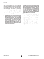
power
8
power
LED
HDD
LED
COM port
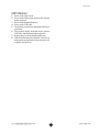
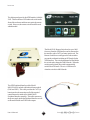
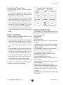
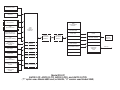
Connect the internal cables to the Peripheral Interface PCB:
• data link radio cable to J12; screw
down
• power cable to J10
• Power LED to J16
• HDD LED to J17
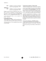
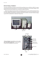
Note: If the power LED does not come
on after power is applied, reverse the
PCB connector. If the HDD LED stays
on steadily after applying power, reverse its PCB connector.
AW O S
AUTOMATED WEATHER OBSERVING SYSTEM
radio
23
User’s Manual