1
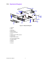
A.1 Exploded Diagram
6
4
5
14
9
8
12
7
12
10
11
3
1
2
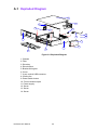
Figure A.1 Exploded Diagram
1: Chassis
2: Filter
3: Drive bay
4: Riser bracket
5: Bracket linking bar
6: Cover
7: 2 port vertical USB connector
8: Cooling fan
9: Power switch button
10: Front mechanical part
11: Power supply
12: Screw
13: Screw
14: Screw
DVS-500 User Manual
20
13