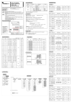
1
Power Cable Connection
■ Use Vinyl insulation wire 0.9~2.0㎟ (Allowed Rating Voltage
300V max) or higher leveled cable for power cable connection.
L
RLY_NO
Be sure to keep L(Hot) and N(neutral) status connection.
Otherwise, it may result for operation default and defect.
!
CAUTION
Φ5.8㎜ or less
N
Terminal Specification
Use M3.5 screw-compatible crimp-on terminals with insulating
sleeve as shown below.
CAUTION
2. DC VOLTAGE INPUT
SHIELD
SHIELD
b
RTD
■ Recommended CR FILTER
▶ Seong Hoo Electronics
▶ HANA PARTS CO.
▶ Songmi Electric Co.,Ltd.
▶ Jiwol Electric Co.,Ltd.
▶ Shinyoug Communications Co.,Ltd.
-
-
R
NOVA300
NOVA300
NOVA300
Class 3 Ground
Class 3 Ground
+
DCmA
R
Class 3 Ground
2. RET
Actuator
+
OUT1+
-
OUT1-
CAUTION
SHIELD
Receiver
(Recorder
etc)
NOVA300
Class 3 Ground
SCR : 4∼20mADC, 600Ω max
SSR : 12VDC min, 600Ω min
+
RET+
-
RET-
R
DIODE
CR FILTER
Display Error and Correction
NOVA300
Class 3 Ground
To prevent electric shock, be sure to turn off the NOVA300 controller and the source circuit
breaker before connection/disconnection of the actuator, receiver as well as wiring.
!
Display
ERROR
ERROR Contents
Correction
E.SYS
EEPROM, DATA Loss
Ask repair
E.RJC
RJC SENSOR Failure
Ask repair
Communication Failure
Comm Cable
CHECK
S.OPN
SENSOR Open
SENSOR CHECK
E.AT
AT Time Out (27h over)
PROCESS
CHECK
Flash Decimal
point of SP
CAUTION
Terminal Arrangement and External wiring
ST390
HBA
RET
12
ALM2
13
RS485
HBA
RET
ALARM
RS485
HBA
21
ALM3
RTX+ 15
15
+ 15
15
ALM3
RTX+ 11
11
+ 11
- 22
22
COM
RTX- 16
16
- 16
16
COM
RTX- 12
12
- 12
4~20mA DC * Contact Rating
250V AC 1A
/30V DC 1A
MAX: 19.2Kbps
TC INPUT
1
2
3
4
5
21
22
23
24
mV/V INPUT
2 +
2 +
3 -
3 -
RTD INPUT
ALARM
1 A
8
ALM1
2 b+
9
ALM2
3 B-
10
4~20mA DC * Contact Rating
250V AC 1A
/30V DC 1A
8
9
10
11
12
COM
TC INPUT
1
2
3
4
5
15
16
17
18
MAX: 19.2Kbps
mV/V INPUT
RTD INPUT
ALARM
2 +
2 +
1 A
6
ALM1
2 b+
7
ALM2
3 -
3 -
3 B-
8
* Contact Rating
250V AC 1A
/30V DC 1A
N
L
100~240V AC
(50/60Hz)
HBA
ALARM
23
23
ALM3
ALM4
24
24
COM
* Contact Rating
250V AC 1A
/30V DC 1A
POWER
RELAY
+ 4
4
NO
- 5
- 5
5
COM
11
12
SSR
N
L
100~240V AC
(50/60Hz)
4~20mA DC * Contact Rating
250V AC 1A
/30V DC 1A
HBA
ALARM
17
17
ALM3
ALM4
18
18
COM
* Contact Rating
250V AC 1A
/30V DC 1A
※ HBA, RET to be purchased separately
ST380
mV/V INPUT
2 +
2 +
3 -
3 -
RTD INPUT
SSR
1 A
2 b+
6
7
8
9
10
COM
RTX+ 21
21
+ 21
22
RTX- 22
MAX: 19.2Kbps
ALARM
RET
- 22
11
ALM1
ALM2
13
COM
14
15
* Contact Rating
250V AC 1A
/30V DC 1A
4~20mA DC
+ 4
+ 4
4
NO
- 5
- 5
5
COM
ST380
ST370
3 -
3 -
RTD INPUT
1 A
2 b+
N
9
3 B-
L
10
100~240V AC
(50/60Hz)
4~20mA DC * Contact Rating
250V AC 1A
/30V DC 1A
SCR
RELAY
HBA
+ 4
+ 4
4
NO
13
- 5
- 5
5
COM
14
Voltage
Pulse
※ HBA, RET to be purchased separately
4~20mA DC * Contact Rating
250V AC 1A
/30V DC 1A
※ HBA, RET to be purchased separately
ST320
SCR
RELAY
RS485
+ 4
+ 4
4
NO
RTX+ 9
- 5
- 5
5
COM
RTX- 10
Voltage
Pulse
mV/V INPUT
RTD INPUT
12 +
TC INPUT
12 +
7 8 9 10
ALARM
11
1213
11 A
13 -
13 -
+ 7
7
ALM2
- 8
8
COM
OUT1
HBA
N
1
23
2
L
4~20mA DC * Contact Rating
250V AC 1A
/30V DC 1A
N
L
24
SSR
※ HBA, RET to be purchased separately
+ 3
RELAY
+ 3
3
- 4
Voltage
Pulse
※ ALM2, RET to be purchased separately
ALARM
SCR
- 4
100~240V AC
(50/60Hz)
100~240V AC
(50/60Hz)
13 B-
1 2 3 4 5 6
MAX: 19.2Kbps
4~20mA DC * Contact Rating
250V AC 1A
/30V DC 1A
Dimension and Panel Cutout
ST390
2 +
OUT1
RET
POWER
12
mV/V INPUT
2 +
SSR
POWER
HBA
TC INPUT
1
2
3
4
5
POWER
RELAY
21 22 23 24
1112 13 14 15
RS485
11
12
13
14
12 b+
1 2 3 4 5
3 B-
SCR
Voltage
Pulse
OUT1
TC INPUT
4~20mA DC
OUT1
SCR
+ 4
Voltage
Pulse
D-egister
0604
0605
0606
0607
0608
0609
0610
0611
0612
0613
0614
0615
0616
0617
0618
0651
0652
0653
0661
0662
0663
0664
0665
0666
0667
0668
0669
* Contact Rating
250V AC 1A
/30V DC 1A
OUT1
SSR
Parameter
IN.RL
IN.DP
BIAS
IN.SH
IN.SL
IN.FL
BSL
O.ACT
CT
OH
OL
HYS.H
HYS.L
PO
RSL
RET
RETH
RETL
COM.P
BAUD
PRTY
SBIT
DLEN
ADDR
RP.TM
RBS
SPSL
RET
+ 21
COM
ST360
D-egister
0407
0408
0409
0411
0412
0413
0414
0416
0417
0418
0419
0421
0422
0423
0424
0426
0427
0428
0429
0501
0502
0503
0504
0505
0506
0507
0601
0602
0603
21
POWER
15
Parameter
AL-2
AL-3
AL-4
AL1.H
AL2.H
AL3.H
AL4.H
AL1.L
AL2.L
AL3.L
AL4.L
A1DB
A2DB
A3DB
A4DB
A1DY
A2DY
A3DY
A4DY
ARW
FUZZY
P
I
D
MR
C.MOD
IN-T
IN-U
IN.RH
ST340
ALARM
* Contact Rating
250V AC 1A
/30V DC 1A
14
D-egister
0001
0002
0006
0014
0105
0121
0122
0135
0136
0201
0203
0204
0205
0206
0207
0208
0211
0212
0216
0217
0218
0301
0302
0303
0401
0402
0403
0404
0406
22
11
12
13
14
15
Terminating
Resistor
Class 3 Ground
RTX- 22
ALARM
ALM1
RTX-
RTX+ 21
MAX: 19.2Kbps
11
RTX-
* Thick Line : READ ONLY
ST370
RS485
RTX-
Parameter
NPV
NSP
MVOUT
ALSTS
A/M
AT
AT-G
US1
US2
SP
LOCK
DSP.H
DSP.L
U.PWD
ONOF
INIT
SPRH
SPRL
U.SLP
D.SLP
SKDV
HBCS
HBCD
HBDB
ALT1
ALT2
ALT3
ALT4
AL-1
External AC
Power
Master
▪ DIODE, CR FILTER
Need to connect direct to RELAY COIL Terminal (SOCKET)
▪ R : RELAY
Rating Specification of RELAY COIL should be used lower than the Contact
Rating of Controller
!
4∼20mADC,
600Ω max
SHIELD
RTX+
D-Registers
2. In case of AC RELAY
ANALOG OUTPUT Connection
1. SSR / SCR
RTX+
■ Up to 31 slave controllers(NOVA300 series instruments equipped with communication
option) can be multidrop-connected.
■ Be sure to connect terminating resistors(220Ω, 1/4W) to slave and master controllers
at communication-channel ends as shown above.
To prevent electric shock, be sure to turn off the NOVA300 controller
!
and source circuit breaker before wiring.
CAUTION
: BSE104R120 25V (0.1μ+120Ω)
: HN2EAC
: CR UNIT 953, 955 etc
: SKV, SKVB etc
: CR-CFS, CR-U etc
1. In case of DC RELAY
External AC
Power
Master
INPUT
SHIELD
+
mV,V
B
INPUT
RTX+
Class 3 Ground
INPUT
A
NOVA300
Controller
SHIELD
■ When using an auxiliary relay or inductance load (L) such as solenoid, be sure to insert
a CR filter(for AC) or diode (for DC) in parallel as a surge-suppressor circuit to reject
sparks, preventing malfunction or damage.
3. DC CURRENT INPUT
NOVA300
Controller
Terminating
Resistor
Use an Auxiliary RELAY
ANALOG INPUT Connection
1. RTD INPUT
CAUTION
NOVA300
Φ3.0㎜ or over
Master Station
To protect electric shock, be sure to turn
off the NOVA300 controller and the
source circuit breaker before wiring.
!
COM
Never touch the terminal in the rear panel to prevent electric shock when
power is supplied to the controller, and Be sure to turn off the electric
power before wiring.
Bind the wires connected to the controller terminals neatly together in
order to prevent electromagnetic wave radiation.
!
Communication Wiring (RS485)
RELAY Connection
4
5
ALM1
6
COM
NO
COM
* Contact Rating
250V AC 1A
/30V DC 1A
4~20mA DC * Contact Rating
250V AC 1A
/30V DC 1A
How to install Mount
ST360
ST340
ST320
ST390
ST370
A
ST360
D
C
F
B
E
MOUNT BLOCK
MOUNT BLOCK
H +0.6
0
Panel Thickness
ST340
ST380
G +0.6
0
1mm~10mm : 390,380,370,360
1mm~ 5mm : 340,320
PANEL
PANEL
PANEL
K +0.6
0
ST320
I*N-J
+2
0
N:the Number of unit
MODEL
A
B
C
D
E
F
G
H
I
J
K
ST390
96
96
11.4
99.6
120
120
92
92
96
4
92
ST380
48
96
11.4
99.6
70
120
45
92
48
3
92
ST370
72
72
11.4
99.6
90
90
68
68
71
3
68
ST360
96
48
11.4
99.6
120
70
92
45
-
-
-
ST340
48
48
11.0
99.6
70
70
45
45
48
3
45
ST320
48
24
3.3
96.7
70
60
45
22.2
48
3
22.2
LATCH
PANEL
MOUNT BLOCK
LATCH
PANEL
1) Cut the mounting panel. (Refer to Dimension and Panel Cutout)
2) Insert the controller into the panel cutout with the rear terminal board facing ahead.
3) Attach the right and left mount and fix it to the panel.(Use driver)