1
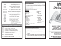
PARTS CHECKLIST
PHONE BASE
TELEPHONE LINE
CORDS (ONE 8 INCH &
HANDSET &
HANDSET CORD
AC ADAPTER
(7.5v/500mA)
ONE 6 FOOT CORD)
WALL PLATE
ADAPTER
CONNECTING YOUR PHONE
USER’S MANUAL
PHOTO TEMPLATE
1. CHECK PARTS LIST
2. PRE-SELECT AUXILIARY FEATURES:
a. AMPLIFICATION: Amplify Override ON / OFF
b. RINGER: Strobe & Shaker / Only Shaker / Only Strobe
3. PHONE INSTALLATION: The phone should be located in
an area where it is easy to see the visual display and lighted
ringer. Choose an area near a telephone wall jack (RJ11C)
and power outlet. The telephone may be placed on a shelf
or table or may be fixed to the wall using the wall plate
adapter (mounting bracket). Begin by removing the clear
plastic Caller ID protective tab.
Desk / Table Mounting
1. Plug the AC power adapter into the jack on the back
of the telephone. Wait until the phone is completely
setup before plugging the AC adapter into the electrical
outlet or surge protector.
2. Connect one end of the 6 ft telephone cord to the line
jack on the back of the phone and connect the other
end to a modular phone jack.
3. Connect one end of the coiled handset cord to the
handset and the other end to the phone base.
4. Lift the handset and listen for the dial tone.
Wall Mounting
1. Adjust he handset hanger tab so that the hook points
up. This will keep the handset from falling out of the
cradle when it is mounted on the wall.
2. Plug the AC power adapter into the jack on the back of
the telephone (complete setup before plugging the AC
adapter into the electrical outlet or surge protector).
3. Plug the 8-inch short phone cord into the telephone
jack on the phone.
4. Insert the wall plate adapter by lining it up with the
holes on the phone, then push the wall plate adapter
in towards the phone and slide the plate upwards until
it is securely seated on the phone.
5. With the wall plate adapter installed, plug the 8-inch
short phone cord into the jack on the wall.
6. Mount phone onto wall jack mounting screws (dry wall
mounting, see page 14.
7. Plug the AC power adapter into the electrical outlet.
8. Connect the handset using the coiled handset cord and
listen for a dial tone.
LOCATION OF CONTROLS
4
3
6
5
7
8
1
2
9
10
11
27
12
13
14
15
28
16
21
26
25
24
23
22
20
18
19
17
Figure 1
01. Hook Switch
02. Handset Hanger Tab
03. Large LCD/Caller ID Screen
04. Left Soft Key
05. Right Soft Key
06. Up/Down Scroll
07. Handset Tone Control
08. Handset Volume Control
09. Play/Stop Key
10. Next Key
11. Previous Key
12. Delete Key
13. MEMO Key
14. Voice Mail Key
15. Call Waiting Key
16. Headset Key
17. Message waiting /
New call LED
18. In Use LED Indicator
19. Visual Phone Ringer
20. Microphone
21. Speakerphone Key
22. Redial Key
23. Amplify Activation Key
24. Emergency Memory Key
25. Prog – Program Key
26. (8) 1-Touch Photo
Memory Dial Keys
27. Lighted Keypad
28. Speaker
If at any time you have questions about your
telephone after reading this manual, please
contact our ClearSounds® Customer Service
Department at 1-800-965-9043.