1
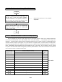
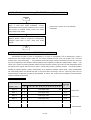
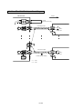
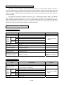
18.1.2 The Procedure of Using FBs-6AD Module
Start
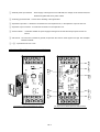
Set the I/O voltage/current (V/I), polarity (B/U), and
the V/I range of each point before installation.
Connect FBs-6AD to the expansion interface on
-------
PLC in series and connect an external 24VDC
Please refer to section 18.1.4 for hardware
explanation.
source and analog output wires to the module.
Directly read the value of the six corresponding
value input registers to obtain the analog input
reading of CH0~CH63.
End
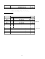
18.1.3 Address Allocation of FBs-PLC Analog Inputs
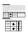
The I/O addressing of FBs-6AD inputs is beginning from the module closest to main unit, it is orderly numbered as
CH0~CH5 (1st module), CH6~CH11 (2nd module), CH12~CH17 (3rd module)…… and increased with occurring order
number, i.e. for each module, it adds with 6 and is totally 64 inputs from CH0~CH63, and they are corresponding to the
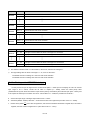
respective internal analogue input register of PLC (so called as IR register) R3840~R3903 as listed in following table.
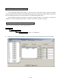
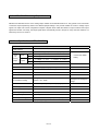
After connecting FBs-6AD to the expansion interface on the PLC, FBs-PLC will automatically detect the number of AD
points. WinProladder will automatically detect and calculate the IRs on the system after connecting to the PLC. Users
may refer to the I/O Module Number Configuration provided by WinProladder in order to find out the exact I/O address of
each expansion module to facilitate programming.
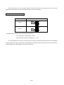
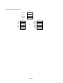
Numeric Input
Content of IR (CH0~CH63)
Register(IR)
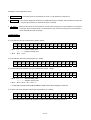
B 1 5 B 1 4 B 1 3 B 1 2 B 11 B 1 0 B 9 B 8 B 7 B 6 B 5 B 4 B 3 B 2 B 1 B 0
Input label
Of FBs6AD
IR+0
14/12 bit ; 14-bit , B14~ B15= B13 ; 12-bit, B12~ B15= B11
CH0
IR +1
14/12 bit ; 14-bit , B14~ B15= B13 ; 12-bit, B12~ B15= B11
CH1
IR +2
〃
CH2
IR +3
〃
CH3
IR +4
〃
CH4
IR +5
〃
CH5
IR +6
Depends on module type
CH X
IR +7
Depends on module type
CH X
IR +8
〃
CH X
IR +9
〃
CH X
18-2
F Bs - 6 AD