1
4-18
PC Operation
GEK-90842
14.
When the verify is complete without error. the Prommmer will display End in the Address/Data
display.
15. Stop the recorder and depress the CLR (Clear) key on the Programmer to end the verify operation.
16. The verify operation will require approximately the same : time as the record operation.
Loading A Program
1 . Install the Programmer and apply AC power to the PC.
2 . Turn the mode switch on the Programmer to the LOAD position.
3 . Apply AC power to the tape recorder and insert the cassette containing the required program.
4 . Adjust the volume control to the setting determined during the verify operation. Adjust the tone
control to its highest setting.
5 . Connect the Programmer (TAPE port) to the tape recorder (EAR input) with the audio cable (gray
with red tracer).
6 . Rewind the tape to the beginning of a previously recorded program. Tape can also be on the blank
area prior to the program, but not on another program. Enter the program identification number (if
previously recorded).
7 . Select the READ key on the Programmer to establish the load operation.
8 . Start the tape recorder by depressing the PLAY key. The load operation now begins.
%’ _
If the CPU detects a program number different than the one entereu III step 6, the programmer will
beep and the display will show PA
.
9 . If the wrong program has been selected, the load operation can be aborted by stopping the recorder
and powering-down the CPU or remove the programmer from the CPU, then reattach and depress
the CLR key.
10 . Any errors detected during the load operation are indicated by an error code being displayed on the
Programmer’s Address/Data display. Error code E21 indicates the tape has an internal parity error.
A steady E28 indicates the play level is wrong and the load should be stopped, volume adjusted, and
the operation restarted (step 6 above).
11 . When the load is complete with no errors, the Programmer will display End in the Address/Data
display and the ON/OFF LED will be off. Stop the recorder and depress the CLR (Clear) key on the
Programmer to end the load operation.
12 . The load operation will require approximately the same time as the record operation.
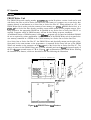
Printer Interface Unit
The Printer Interface Unit (catalog number IC61OPER151) provides an interface between a Series One
or Series One Plus PC and a printer for the purpose of providing a convenient means of obtaining a
hard-copy printout of the program residing in the PC’s user memory. It can also be used with a Series
One Junior PC. The format of the printout is switch selectable and can be either Boolean (mnemonic) or
ladder diagram format. Many readily available, inexpensive printers can be used with the Printer
Interface Unit.
A 6’ (2m) Printer Interface cable and an external power supply cable are included with the Printer
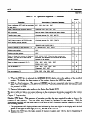
Interface Unit. Printer Interface Unit Specifications are listed below in table 4-3