1
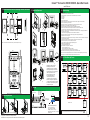
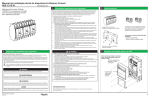
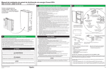
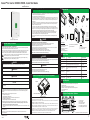
Conext™ CL Inverter 20000E/ 25000E - Quick Start Guide www.SESolar.com Correct Installation Distances, Mounting Positions, Dimensions H J Mounting Sequence 23.6in (600mm) 23.6in (600mm) A (e) (f) 36in (914.4mm) (d) Note: It is recommended to install the inverter away from direct exposure to sunlight. (g) (i) 3.9in (99mm) 4.7in (119.3mm) 15.8in (401.3mm) There are three indicator lights (LED) below the LCD. The left and middle indicator lights are green and the right indicator light is red. The three indicator lights together indicate the inverter status. K (j) a. Mounting the wiring box bracket b. Mounting the Inverter bracket c. Mouting the wiring box on the bracket d. Fastening the wiring box to the bracket e. Opening the front cover of the wiring box f. Removing the connector cover g. Anchoring the connector cover h. Inverter assembly- side view i. Inverter assembly- front view j. Locking the inverter to the wiring box k. Inverter and wiring box- exploded view l. Locking inverter and wiring box connector m.Inverter rear view with mounting bracket n. Closing the wiring box 16.3in (414mm) (m) H 0.9in ~ 36in (22.8mm) (914.4mm) 7.8in 5in (198.1mm) 15.7in (398.7mm) (127mm) 25.7in (652.7mm) Mounting Sequence I (n) PV input: PV connector Français Startup... ESC Communication: [1x] M25 cable gland [1x] RJ45 Ethernet [2x] RJ45 Modbus [1x] Dry contact [1x] RPO connector Select Time Zone TimeZone Setting 4 OK Date & Time 25/06/2014 13:54 <selected language > Español 75% Date & Time OK Confirm language Done ESC Press OK to confrm, ESC to cancel OK Australia Perth Australia Adelaide Australia Darwin Australia Canberra Australia Melbourne ESC 1 Date & Time 4 OK OK 0 25/06/2014 13:54 0 0 0 Done Select Done, Press OK to move next ESC Confirm Country Select Country Password Date & Time Select Time Zone Italy LV India LV North America OK <Country> Germany LV Press OK to submit ESC ESC OK Confirm Country Press OK to confrm, ESC to cancel ESC 1 2 Confirm W-box Select Wiring box 100mm OK ESC Modbus Address 10 OK Press OK to Confirm <Modbus settings> Done Press OK to confrm, ESC to cancel ESC Confirm Modbus Modbus Settings OK Confirm Wiring box <selected Wiring Box> ESC Press OK to confrm, ESC to cancel OK ESC 2 (2x) M8 screws* FIRST TIME POWER UP SETTINGS Password: ‘1234’ Rebooting Syatem Please wait... Minimum cable requirement Earthing terminal (2x) Locating pins* *(not included in the package) Language OK PVSCL1825NA100 PVSCL1825NA200 PVSCL1825NA201 PVSCL1825NA300 PVSCL1825NA301 20mm (5x) M8 screws* Language English Wiring AC output: [1x] M32 cable gland (a) First Time Power Up Screen (l) (k) 12.5in (317.5mm) 37.1in (942.3mm) 4.1in 15.7in (398.7mm) 20.4in (518.1mm) 23.9in (607mm) 3.2in (81.2mm) 23.6in (599.4mm) (104.1mm) (h) Commissioning Start up procedure: 1. Ensure that the DC and AC breaker are turned OFF. 2. Complete the wiring as per the instructions in the Installation and Operation Manual. AC wiring DC wiring Earthing Communication Interface 3. Check the polarity of the DC wires and ensure that the maximum DC voltage is not more than 1000 V. 4. Ensure to place the string protection fuses*. 5. Ensure proper insertion of communication interface cables to the appropriate connectors. 6. Ensure the dry contact and RPO connections are wired properly. 7. Ensure all the cable glands are sealed properly after completing the terminations. 8. Check the http://solar.schneider-electric.com/product/conext-cl/ for the latest firmware version. If the version on the inverter and website matches, follow step 10 or else step 9. 9. Turn on AC or DC and then connect the USB drive with the latest fimware version, to the appropriate USB device socket and press the OK button. The inverter now starts upgrading the new firmware available in the USB drive. 10. Ensure all the conduit entry provisions are sealed properly after completing the terminations. 11. Replace the cover on the wiring box. 12. Turn ON the AC breaker (external) and ensure that the grid is connected to the inverter. The inverter will boot up and complete the Power on Self test. 13. On successful completion of the Power on Self test, follow the first time power up settings. 14. After the first time power up, turn ON the DC disconnect switch. If there is sufficient sunlight, the inverter will start producing power. 15. Check the status of the indicator light. The PV status LED should be green. 16. If the PV status LED is not green, check whether: All the connections are correct. All the external disconnect switches are closed. The DC disconnect switch* on the inverter is in the “ON” position. *The DC disconnect switch and string protection fuse are not part of the Base model. 7.8in (200mm) G (b) (c) Copyright © 2014 Schneider Electric. All Rights Reserved. All trademarks are owned by Schneider Electric Industries SAS or its affiliated companies. AC : 400 V, 33 A (25 KVA) DC : 1000 VDC, 40 A/ MPPT Earthing: 6 to 10 mm2, Cu, 900 C Remote Power Off : 0.33 mm2, 2 wires, 30 m distance (max) System Reboot For more information about the Conext CL Inverter, see the Installation and Operation Manual. 2