1
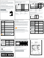
3 Installation of the IG325/2 For the use of the device in a surrounding with higher protection requirements, SWARCO TRAFFIC SYSTEMS offers special enclosures (type GHIG300 / GHIG301). Before switching on the power supply, the device must be plugged onto the socket. 3.1 Special notes on the loop The safe functioning of the device depends essentially on the technically proper installation and laying of the loops, since the loops are the sensors of the device. The loop feed cable must be drilled approx. 20 – 50 times per meter and must be laid in distance from life wires. For further information see “Laying of Loops” (available at www.swarco.com/sts). 4 Device adjustments A After every device adjustment a new alignment must be effected by pushing the reset-button (E). B G C I H D F 4.3 Function selection switch (D) Switch 3 on Impulse when leaving the loop active Switch 4 on Switch-on delay on Switch 5 on Automatic alignment active when fault The switching signal is switched-off with a delay of 2 seconds after the loop is vacant (not in impulse mode). The attenuation of the first loop is registered in the detector but no relay is switched yet. Only if the second loop is attenuated at the same time, the relay of the channel which was attenuated the last is switched and stays switched until the second loop is clear again. This function is valid for both directions. The detector switches the channel-relay only after the loop is vacant. The adjustment is only active if additionally the channel status impulse mode (channel switch (C) S4, S8) is chosen. The switching signal is emitted when the loop is attenuated for more than one second. When there is a loop fault, the detector aligns anew automatically after approx. 12 seconds. If the fault lasts for a longer period of time, the detector keeps trying to align until the fault is eliminated. The relays and LEDs stay in “fault” position until the alignment is effected. Switch 6 on A loop fault is indicated on the LEDs and addionally the according channel relay is switched Detection by on. For a combination with switch 6 on, switch 5 fault active must by all means rest on off, since otherwise the detector aligns anew after 12 seconds and a vehicle which might stand on the loop will not be detected anymore. 13 Description Possible cause Vehicle movement on the loop Loop is moved mechanically Correction Keep loop clear during alignment Control laying of loop, observe documentation “Laying of loops“ ElectromagEliminate cause of counetic coupling pling, observe documenonto the loop tation “Laying of loops“ Yellow LED continuously blinking After every change of adjustment resp. correction of error the reset button (E) must be pushed! 6 EC Conformity 6.1 Requirements for the usage according to regulations Requirements acc. to ETSI EN 300330-1 (2002-12) For the antenna factor (loop area A in m2 multiplied by the number of loop windings N) the following is imperative: N*A ≤ 60 m2 Product Class 2: Maximum length / width Area Number windings 16 IG325/2 Version „Tor“ (gate) (Type: IG325/2S.T. / IG325/2W.T. / IG325/2ST.T.)* * indicated on right label of device channel switch (C) sensitivity channel1 channel2 7 (high) 6 5 4 (med) 3 2 1 (low) S5 S6 S7 hold time: S8 S1 S2 S3 S4 on on on on=impulse / off=static off on on ‘’ on off on ‘’ off off on ‘’ on on off ‘’ off on off ‘’ on off off ‘’ test mode relay released off off off off test mode relay released off off off on default setting: sensitivity 4 (med) and static hold time. sensitivity: channel 1 channel 2 adjustable in 7 levels channel switch (C) channel switch (C) S5-S7 S1-S3 hold time: static (presence) or impulse 100 ms channel 1 channel 2 channel switch (C) channel switch (C) S8 S4 IG325/2 Version „Verkehr“ (traffic) (Typ: IG325/2S.V. / IG325/2W.V. / IG325/2ST.V.)* * indicated on right label of device channel switch (C) sensitivity channel1 channel2 4 (high) 3 2 1 (low) S5 S1 on off on off S6 S2 on on off off S7 S3 on off on off off off off off off off default setting: sensitivity 3 and 2h hold time. test mode relay released test mode relay released channel 2 channel switch (C) S1-S2 hold time: channel 1 adjustable in 4 levels channel switch (C) S7 - S8 channel 2 channel switch (C) S3 - S4 4.2 Adjustment of frequency with the frequency switch (G) S1-S2 in order to avoid couplings caused by nearby loops. Two or more detectors must not operate on the same frequency. 11 5 Alignment and fault diagnosis 5.2 Detection and correction of errors 5.1 Alignment When switching on the power supply, when there are voltage interruptions or when the reset switch (E) is pushed, the loop detector automatically aligns itself to the connected loops and switches the relays to switching position “loop not attenuated”. During the alignment period the yellow power-LED (F) is blinking for a few seconds. With a low sensitivity the detector is ready for operation at once. After the alignment the power-LED (F) keeps glowing. During the alignment phase there may be no vehicle on the loop since it will not be detected. Display of switching and failure status The switching mode “loop occupied“ is indicated by a glowing green channel-LED (A) resp. (H). Loop failure caused by a short-circuit, an interruption or a loop inductivity outside of the permitted range is indicated by a glowing red channel-LED (B) resp. (I). S1 left* right* left* right* S2 left* *position of switches left* (see also front panel) right* right* default setting: 4 (high) Description Possible cause Detector does not There is no align, yellow LED power supply does not glow for detector Red LED glowing, Detector green LED blinking detects “loop long, long, long interrupted“ Red LED glowing, Detector green LED blinking detects “loop short, long, short short-circuited” Test mode Yellow and green relay tightened is active LEDs glowing, relay permanently Loop is moved tightened mechanically Correction Check connection to power supply Check loop and loop connection Check loop and loop connection Deactivate test mode (see table Adjustment of sensitivity and hold time) Control laying of loop, observe documentation “Laying of loops“ Test mode re- Deactivate test mode lay released is (see table Adjustment of Detector does not active sensitivity and hold time) switch in spite of Progressively increase effected alignment Chosen sensitivity is sensitivity until vehicles too low are detected correctly 14 15 Constraints for the compliance with EN 300330-1 According to the stated formula, the following loop windings in dependence to the loop area are recommended: 6.2 EC Declaration of Conformity Product Class acc. Number Area to EN 300300-1 windings 2 (1 – 3) m2 6 2 (3 – 5) m 5 2 (5 – 10) m 4 2 (10 – 15) m 3 2 (15 – 30) m 2 2 3 (30 – 60) m 1 Lloop [µH] 100 - 300 80 – 260 160 – 320 180 – 280 80 – 180 40 - 100 Operating frequency range (L = 15 µH – 400 µH) 20.05 kHz < f < 70 kHz Total inductivity (loop + feed cable): Specification: Ltotal< 400 µH Example: Loop inductivity 200 µH; feed cable inductivity < 200 µH with 100 µH / 100 m: length of feed cable < 200 m Requirements acc. to DIN EN 60950 The device has basic insulation. Product Class 3: 30 m < 30 m2 ≥1 Area Number windings > 30 m2 1 © 2010 All rights reserved 17 S8 hold time S4 on 0.1s on 4.5min. off 2h off off on sensitivity: channel 1 adjustable in 4 levels channel switch (C) S5-S6 frequency switch (G) frequency 4 (high) 3 2 1 (low) 12 E 10 Switch 1 on Switch-off delay on Switch 2 on Directional logic active 4.1 Adjustment of sensitivity and hold time 18