1
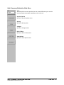
RJ+PJ Filters Menu
RJ+PJ HPF
Natural Rolloff – Uses the –3dB frequency as the “Natural Rolloff”. This is a “Natural
Rolloff” because the amount of data acquired by the tool naturally limits the lowest
frequency "seen".
Brickwall – Brick wall cuts off any frequencies below this value. Note that the –3dB
frequency should be lower than the brick wall cutoff or the natural rolloff will have a
filtering effect.
NOTE: Depending on the frequency of the clock being measured, it is possible that
the Nyquist Frequency of the clock (1/2 the clock rate) could intrude into or be below
the region chosen as the First Order filter frequency. Additionally, if the Fmax Divider
is set at any value other than one, this will eliminate any frequency content above
divided Fmax. For example, if measuring a 400MHz clock, the Fmax or Nyquist is
200MHz. Therefore, a First Order filter set to 20MHz would be 20dB down at
200MHz. But, if the Fmax divider is set to '2', then the "nyquist" or "Fmax" would be
100MHz and would cut into the first order filter. In this case, the RJ(RMS) value
measured may not contain the same spectral content as did the measurement with
Fmax set to '1'. The reported RJ(RMS) value would be lower with the Fmax set to '2'.
High Pass Freq (MHz)
Lower frequency limit for the window over which RJ and PJ is calculated. Default is
Corner Frequency. This setting cannot be set lower than the corner frequency.
RJ+PJ Low Pass Filter (LPF)
Nyquist – This is the default. The highest frequency that the tool can measure is ½
the clock rate (or the Nyquist).
First Order – Enter a -3dB frequency. This filter does not eliminate all the jitter
energy above this frequency (it is not a brick wall filter). The frequency components
or spectral content above this frequency will still contribute to the RJ(RMS) as
displayed from the 1-sigma plot. (see figure)
NOTE: Depending on the frequency of the clock being measured, it is possible that
the Nyquist of the clock (1/2 the clock rate) could intrude into or be below the region
chosen as the First Order filter frequency. Additionally, if the “Fmax Divider” is set at
any value other than one, this will eliminate any frequency content above divided
Fmax. For example, if measuring a 400MHz clock, the Fmax or Nyquist is 200MHz.
Therefore, a First Order filter set to 20MHz would be 20dB down at 200MHz. But, if
the “Fmax Divider” is set to '2', then the Nyquist or Fmax would be 100MHz and
would cut into the first order filter. In this case, the RJ(RMS) value measured may
not contain the same spectral content as did the measurement with Fmax set to '1'.
The reported RJ(RMS) value would be lower with the Fmax set to '2'.
Low Pass Freq (MHz)
Upper frequency limit for the window over which RJ and PJ is calculated. Default is
the Nyquist frequency.
Back
Returns to the previous menu
HIGH FREQUENCY MODULATION ANALYSIS
©WAVECREST Corporation 2002
Page 9 of 12