1
Analog and Frequency Inputs | 10
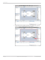
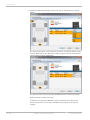
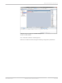
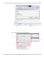
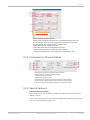
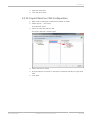
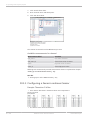
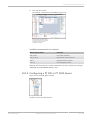
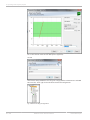
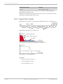
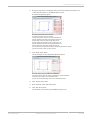
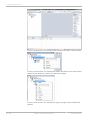
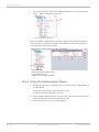
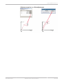
Fig. 8: After sending configuration
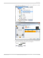
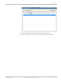
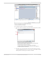
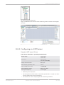
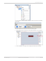
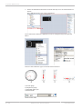
Right click MSI 60 Front left and create measuring views. It shows raw and physi‐
cal value.
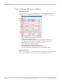
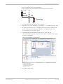
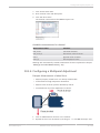
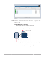
10.3.5 Configuring an LVDT Sensor
Example: LVDT sensor 50 mm
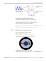
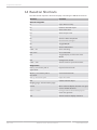
From sensor data sheet – operating characteristics:
Stroke range
± 1.00 inch
± 25.4 mm
Sensitivity
0.8 V/V/inch
31.5 mV/V/mm (C)
Output at stroke ends
800 mv/V
Non‐linearity (% of FR), max.
± 0.25
Input voltage, sine wave
3 VRMS (B)
Input frequency range
400 Hz to 5 kHz
Test input frequency
2.5 kHz (A)
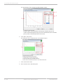
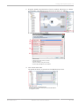
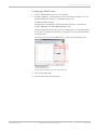
▪ Sensitivity 31.5 mV/V/mm
▪ The zero position of the sensor is internally represented as +2,500 mV, there‐
fore the Offset must be set to 2,500 mV.
▪ The sensor has a linear output signal with sensitivity and offset.
Bosch Motorsport
Modular Sensor Interface MSI 60
69 / 108