1
ISA110 Manual
19/1/2000
10:24 am
Page 6
Signal Connections
Getting to Know the ISA110
On
Applies power to the unit.Turn on the ISA110
before powering up devices to which the outputs
are connected.
XLR (Audio) Inputs and Outputs
All 3-pin XLR audio connectors (Output,
Mic/Line Inputs) are wired as follows:
Pin 1
Screen/Chassis
Pin 2
Audio 0°
Pin 3
Audio 180°
O/L LED
Insert Send and Return
1/4” Jack wired as
Tip
Ring
Sleeve
This LED illuminates when the peak signal level
reaches or exceeds +20dB, or when the peak
signal level reaches 6dB below clipping.The signal
is monitored after the EQ stage.
Occasional short-duration peaks which may
cause the LED to blink will not normally cause
audible distortion, but if the LED is lit constantly,
the level in the appropriate section of the module
should be reduced to prevent overloading.
follows:
Audio 0°
Audio 180°
Screen/Chassis
Mic IP & Line IP
Either of these inputs may be used as the main
input to the ISA110.
Input Stage
Insert Return
This is used as the insert input point after the
Mic Pre and before EQ.
Insert Send
This is used as the insert output point after the
Mic Pre and before EQ.
Output
Two input options are provided to give
compatibility with Mic or Line sources.
This is a balanced output after the EQ.
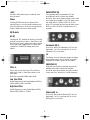
Mic
Mic input sensitivity is switched from -60dB to
0dB in 6dB steps. Phantom power is available on
the rear panel XLR for condenser mics when
+48V front panel switch is pressed.
Line
A Line input is available on XLR, with a switched
gain control giving a range of +/-18dB in
6dBsteps.
Trim
The TRIM control provides additional variable
gain of 0 to 10dB.
4