1
s
XT65/XT75 Hardware Interface Overview
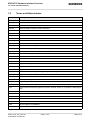
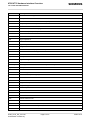
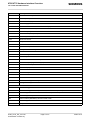
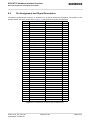
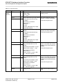
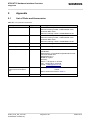
6.5 Pin Assignment and Signal Description
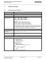
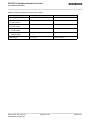
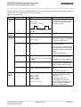
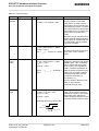
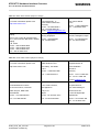
Table 17: Signal description
Function
Signal name
IO
Signal form and level
Comment
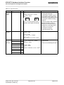
SPI
SPIDI
I
Serial
Peripheral Interface
I2CDAT_SPIDO
O
VOLmax = 0.2V at I = 2mA
VOHmin = 2.55V at I = -0.5mA
VOHmax = 3.05V
If the Serial Peripheral Interface is
active the I2C interface is not available.
SPICS
O
VILmax = 0.8V
VIHmin = 2.15V,
VIHmax = VEXTmin + 0.3V = 3.05V
USB
VUSB_IN
I
VINmin = 4.0V
VINmax = 5.25V
USB_DN
I/O
USB_DP
I/O
Differential Output Crossover voltage Range
VCRSmin = 1.5V, VCRSmax = 2.0V
I2CCLK_SPICLK O
Driver Output Resistance
ZDRVtyp = 32Ohm
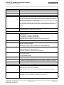
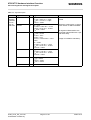
Digital
Audio
interface
DAI0 (USC0)
I/O
DAI1 (USC1)
I/O
DAI2 (USC2)
I/O
DAI3 (USC3)
I/O
DAI4 (USC4)
I/O
DAI5 (USC5)
I/O
DAI6 (USC6)
I/O
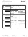
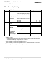
GPIO1
General
Purpose
Input/Out- GPIO2
put
GPIO3
I/O
I/O
I/O
GPIO5
I/O
GPIO6
I/O
GPIO7
I/O
GPIO8
I/O
GPIO9
I/O
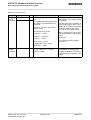
GPIO10
I/O
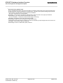
All electrical characteristics
according to USB Implementers’
Forum, USB 2.0 Full Speed Specification.
Without Java: USB port
Under Java: Debug interface for
development purposes.
If lines are unused keep pins open.
DAI0…DAI6 are configurable as
PCM interface
VILmax = 0.8V
VIHmin = 2.15V
VIHmax = VEXTmin + 0.3V = 3.05V
VOLmax = 0.2V at I = 2mA
VOHmin = 2.55V at I = -0.5mA
VOHmax = 3.05V
I/O
GPIO4
XT65_XT75_HO_v00.130
Confidential / Preliminary
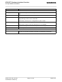
VOLmax = 0.2V at I = 2mA
VOHmin = 2.55V at I = -0.5mA
VOHmax = 3.05V
If lines are unused keep pins open.
VILmax = 0.8V
VIHmin = 2.15V,
VIHmax = VEXTmin + 0.3V = 3.05V
Page 39 of 67
All pins which are configured as
input must be connected to a pullup or pull-down resistor.
If lines are unused (not configured) keep pins open.
Alternatively, the GPIO10 pin can
be configured as a pulse counter
for pulse rates from 0 to 1000
pulses per second.
2006-10-12