1
•
•d
2.4
INITIAL OPERATION AND CHECKOUT
2.4.1 Inspectio n after Installation
After completing the installati on, it is necessary to assure that all
the ste ps of the installation were accomplished in accordance with the
instruction s.
In parti cular. inspect to insure that the cables are not crimped or
damaged and the input volta ge connected accurat ely ; the securing bolts
of all equipment is tightened ; and that the connect ion of the power cable
shield is made properly to RF ground.
2.4.2 Operational Check
Apply power t o radar and swit ch to st a ndby by pressing
ST·BY/ OFF I switch. In approximatery 90 seconds the sign on the
screen should change from "LDR 9910" to "READY".
Pr ess the IX·MIT/ o FF I switch and observe presence of a sweep.
range rings , and heading line. While selecting different ranges, observe
that the sweep is the correct length and has two range rings on each scale.
Set the GAIN control and observe the presence of targets and noise.
Set SEA CLUTTER control on 1/2nm scale and note the reduction of
close in ta rgets.
After approximately 10 minutes of operation, set the TUNE control
and check that maximum target returns occur at the center of the control
range. If tuning control is off center, refer to section 4.1.
I
2.4.3 Relative Bearing Alinment
Th is alinment must be made when the radar unit is installed . Failure
to perform this procedure can result in incorrect target bearing readings.
Proceed as follows :
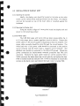
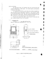
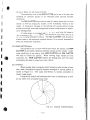
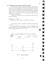
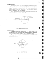
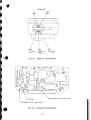
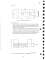
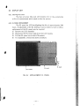
1) Locate and remove the soft plastic cover located on the bottom of the
display unit. Refer to figure 2-4.
2) Identify a suitable target (e.g., buoy, etc.) preferably between 1 and 2
nm in range on the screen.
3) Visually locate the target and line the bow of the vessel up with the
target.
4) Locate the bearing of the target on the display.
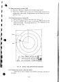
5) Put the EBL marker on the target.
6) · Set BRF (Bearing Adjust Fine) at its mid position .
7) Pr ess the RINGS key until th e buzz er sounds and the display indicates
"BEARING ADJUST".
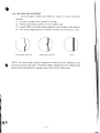
8) Adjust BRC (Bearing Adjust Cours e) so that the target will be
within ± 10 degree of the heading line on the display and simulta-
- 15-