1
Performance Tests
2
Output Standing Wave Ratio (SWR) Test
Description
Connector mismatch is the largest single contributor to measurement
uncertainty, so this specification must be warranted to provide assurance
of instrument accuracy. The 1 mW power reference level test must be
carried out prior to this test, as the VSWR specification is only valid at 1
mW. This test measures VSWR by equating relative powers (measured by
the test system power meter and its sensors) when the power reference is
exercised under different load conditions.
Equipment
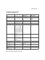
• Required test equipment:
1 unit of 8753ES/ ET network analyzer
1 unit of 85032B Type N calibration kit
1 unit of E4419B or E4417A dual channel power meter
2 unit of 8481D power sensor
2 unit of 11667A #001 power splitter
1 unit of 20dB pad, male to female (e. g. 8491A)
1 unit of 30dB pad (e. g. 11708A reference attenuator)
2 unit of 11730A power sensor cable
• An alternative network analyzer can be used, as long as it can measure
S11 in the 45 MHz - 55 MHz range
• Either of these E4419B or E4417A power meters can be used
• These specific models of power sensors and power splitters must be
used
• Any type of pad can be used (as long as there are no additional mating
connections, or differing pad values)
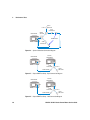
• 1 unit of 11667A, 1 unit of 8481D and the 30 dB pad combine to create
the ‘Calibration System’
• 1 unit of 11667A, 1 unit of 8481D and the 20 dB pad combine to create
the ‘Measurement System’
N1911A/1912A P-Series Power Meters Service Guide
25