1
Index
power supply
uplink ports
LINK LED
power source interruptions, effects on chassis
C-3
2-7
power supplies
1-4
AC-input power supplies installation procedure
1-11
AC-input power supplies removal procedure
4-9
4-8
DC-input power supplies removal and replacement
procedure 4-2
M
management port pinout
DC power cable leads color coding
B-11
LEDs
C-3
troubleshooting
N
2-12
C-3, C-4
power supply
troubleshooting
NEBS ground
power supply, blank cover (Catalyst 4948E)
See system ground
note definition
power supply, blank cover (Catalyst 4948E-F)
xi
power supply fan speeds (table)
O
operating temperature, chassis
1-7
organization, document (table)
ix
PS1 LED
1-11
PS2 LED
1-11
P
kit
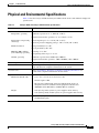
physical and enviromental specifications tables
transceivers
1-GB SFP transceivers
1-7
pinout
required tools
rack-mounting guidelines
2-2
i-x
AC-input power supplies
4-8
DC-input power supplies
4-2
4-10
accessing
3-22
1-5
description
power
troubleshooting
3-4
RESET switch
POST
power cords
3-4
fan tray
B-11
connecting source DC
A-5, A-8, A-14
removal and replacement procedures
physical characteristics
LEDs
1-6
3-5 to 3-8
related documentation
B-5
Catalyst 4948E and Catalyst 4948E-F
1-6
R
rack-mounting
management port
C-4
function
3-14
C-2
1-5
rollover cables
description
A-8
1-5
B-11
identifying colors
power requirements
B-12
AC-input power supplies branch circuit
requirements 2-12
site preparation
2-11
UPS, selecting a UPS
2-11
Catalyst 4948E and Catalyst 4948E-F Switch Installation Guide
IN-4
OL-21561-02