1
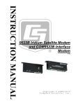
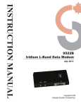
9522B & COM9522B Iridium Data Modem
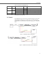
Table 1. Equipment List for Base and Remote Stations
Base Station
Remote Station
9522B L-Band Data Modem
9522B L-Band Data Modem
MB3 Mounting Kit (optional)
Iridium antenna plus cable
Iridium antenna plus cable
COM9522B
COM9522B
Iridium SIM card (comes with modem)
9876-001 Null Modem Cable (1ft lead)
SC932A with an extra SC12 (Only required if
using CSI/O port of datalogger)
Iridium SIM card (comes with modem)
SC110 9-pin male DTE to bare leads (Only
required if using a datalogger COM Port)
1.3 Hardware Overview
Table 1 lists the hardware typically used for both a Base and Remote station. Tables
2 and 3 list common wiring for both the remote and base stations. Figures 1 to 3
represent the typical configurations of the Base and Remote stations. Please refer to
Appendix B for a thorough description of the installation procedure for both the Base
and Remote stations.
WARNING
Be sure that the antenna is connected to either of the
modems before applying power, as damage to the
equipment may occur.
Table 2. Remote Station COM9522B Wiring
Hardware
ComPort
Description
Colour
Antenna
9522B
COM9522B Interface
Power Control
Yellow
Ground
Modem Power
Serial Communications
“DCE Device”
“Datalogger”
Black
Red
9876-001
SC12
SC12
COM9522B
2
9876-001
RS232
SC932A
(optional)
CS I/O
Connection
“ANT” SMA connector to antenna cable
using C2626 adaptor
26-pin ribbon cable connector
Control Port Datalogger (5V power
trigger)
G – Datalogger
+12V (Direct to Station Power Supply)
9-pin connector of COM9522B
9-pin connector of COM9522B
CS I/O port of Datalogger