1
If the submaster droop is negative (actual value less
than reference value), the SCV should be increased for
HCV and IGV loops and decreased for CC and ECON
loops.
8. Once the submaster loop is adjusted, remove all forced
values and proceed with verification and adjustment of
master loop.
9. To check the master loop:
Create a demand in the master loop. For example:
Force the actual space temperature to a value less than
the heating set point or greater than the cooling set
point.
10. Observe system (loop) response for 10 to 20 minutes
to verify stable control. After 10 minutes, if the output
continues to swing from full open to full closed, lower
than MLG and observe again.
11. Do this until the loop operation is stable. After 10 minutes, if the loop does not seem to respond (little change
in submaster reference), increase the MLG and
observe again. Do this until stable operation is
achieved.
12. Once satisfied with loop operation, remove all forced
values which may have been initiated during this
procedure.
13. Repeat Steps 1-12 until all loops have been checked.
NOTE: For better tuning, the CCN ComfortWORKS® software or Service Tool should be used to adjust the proportional
and integral terms. Contact your Carrier representative for
more details.
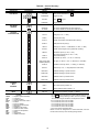
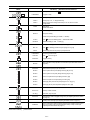
Press
after a code has been displayed to expand the code
into a full definition.
Press
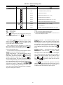
on the keypad to determine a configured
alert limit. Then access the
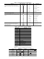
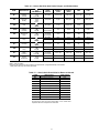
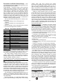
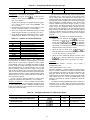
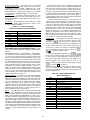
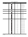
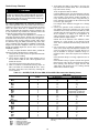
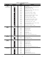
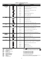
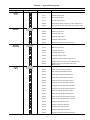
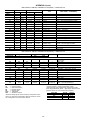
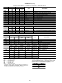
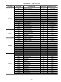
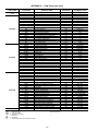
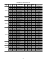
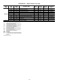
subfunction per Table 14 to determine the actual value being monitored. Table 14 also indicates the acceptable high and low limits (both Occupied and
Unoccupied modes) for the configured alerts and defines the
factory preset default values. The alert will return to normal
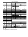
once the alert channel meets the criteria. The criteria for return
to normal is the high limit minus a constant or the low limit
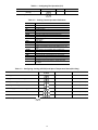
plus a constant. See Table 15 for the list of constants. Items
having no constant return to normal as soon as the unit returns
to the acceptable range (between low and high limits).
Certain analog alerts are only generated when the unit is in
the Occupied mode. These alerts are IAQ (Indoor Air Quality),
OAC (Outdoor Air Quality), and BP (building pressure). Alerts
will not be generated when the controls are in the Unoccupied
mode, even if the sensor value is outside the configured limits.
The OAT (outdoor-air temperature) and OARH (outdoor-air
relative humidity) analog alerts are monitored at all times and
generate alerts whenever the sensor value exceeds the corresponding alert limits.
The SAT (supply-air temperature), SPT (space temperature), RAT (return-air temperature), SP, and RH have alert
limits for both the Occupied and Unoccupied modes (see
Table 14). A 30-minute delay is used when changing from Unoccupied to Occupied mode for these alerts. If an alert condition exists in the Unoccupied mode, no alert will be generated.
If the alert condition still exists 30 minutes after unit enters
Occupied mode, an alert will be generated at that time.
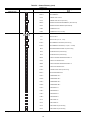
(Modes) — There are 21 different operating modes
available. The operating mode codes are displayed to indicate
the operating status of the unit at a given time. To enter the
modes subfunction, press
and use the
to determine
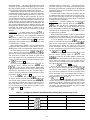
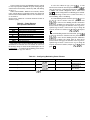
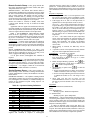
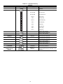
if more than 1 mode is in effect. See Table 48 for a list of the
modes and mode names.
UNIT OPERATION
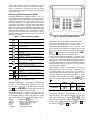
Unit Operation information can be accessed through the
HSIO keypad and display (field-installed accessory). See the
Keypad and Display Module section on page 9 for information
on using the HSIO. The Status Function is provided to allow
the user to access unit operation information.
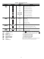
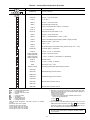
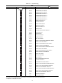
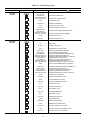
Status Function — This function shows the current status of the alarm and alert codes, operating modes, capacity
stages, operating set point, all measured system temperatures
and pressures, superheat and saturated condensing temperature
values, pressure switch positions, analog inputs, switch inputs,
system component status, and unit standby/run (disable/enable)
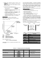
capability. See Table 54.
(Alarms) — Alarms are signals sent by the processor
that one or more faults have been detected. Each fault is
assigned a code number which is reported as an alarm code.
Refer to Alarms and Alerts section on page 72 for specific
alarm information. These codes indicate a failure that causes
the unit to shut down, terminate an option, or results in the use
of a default value as a set point.
To view all current alarms, press
to enter the alarm
displays and then press
to move to the individual alarm
displays. Press
after a code has been displayed to expand
the code into a full definition.
Refer to the Controls and Functions section on pages 8-34
for a detailed explanation of each mode.
(Stages) — This subfunction displays the information
about the current stage. A capacity stage number, from 0 to 11
for cooling and 0 to 2 for heating is displayed to indicate the
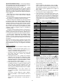
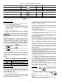
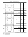
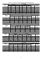
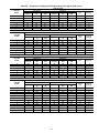
number of active stages. See Tables 55 and 56 for compressor
loading sequences. To access the cooling stages function, press
and press
to display the number of cooling stages
in operation (COOL). Press
to display the following:
1. Cooling Percent Capacity (CPC) — Percent of total
unit cooling capacity being utilized.
2. Heating Stages (HEAT) — The number of active heating stages.
3. Heating Percent Capacity (HPC) — Percent of total
unit heating capacity being utilized.
4. Sum/Z Ratio (SMZ) — Load/unload factor is used to
determine when compressors and unloaders will be
staged. This factor indicates when the addition or subtraction of a step of capacity will occur.
(Set Point) — This subfunction displays the operating
set points that are currently in effect, either occupied or unoccupied. To access the control set point function, press
and press
to display the current control set point.
When a diagnostic code is stored in the display and the unit
automatically resets, the code is entered into the alarm history.
Codes for safeties, which do not automatically reset, are not deleted until the problem is corrected and the machine is switched
to standby, and then back to run mode.
(Alerts) — There are over 20 input channels of alerts
which are compared against their configured alert limits. If any
channel is detected outside of these limits, the corresponding
alert number will be displayed after pressing
to determine if any alerts are present. The
will display first alert.
NOTE: If unit is programmed for CV operation, this will be
the cooling submaster reference value for cooling and the heating set point for heating. For units programmed for VAV
61