1
Variable Air Volume (VAV) Features — The 48/
Factory-Installed Components
50AK,AY units are designed to operate in VAV applications. As
standard, the units include a supply fan VFD to control the supply cfm and duct pressure. The units are designed to control the
leaving-air temperature in cooling to configurable set points.
The control, depending on the selected options and accessories,
will operate in one of three primary modes which are heating,
ventilating and cooling. Initiation of these modes is configurable
from the return air temperature sensor, which is factory supplied, or from a space temperature sensor.
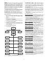
Some special features on VAV applications are:
• Provide cooling control to a supply air temperature in both
occupied and unoccupied modes.
• Supports morning warm-up heating mode which is used
when changing from unoccupied to occupied mode.
• Supports an optional space temperature sensor for mode
control and supply air temperature reset.
• Interface with DAV (Digital Air Volume) control systems
through linkage.
• Support of static pressure reset when used with DAV
systems.
• If space sensor is equipped with an override feature, the
sensor will allow operation during the unoccupied period
for a fixed length of time (1 to 4 hours).
• Control of two stages of heat to maintain return-air
temperature.
• Multiple stage gas heating controlled to a supply air temperature set point if equipped with the staged gas heat option
for use in supply air tempering.
• Base unit control supports a Heat Interlock Relay (field
supplied) to signal the VAV terminal devices to operate at
minimum required airflow for the heaters during heating
operation.
• Controls the operation of the supply fan VFD to maintain a
configurable supply duct static pressure set point. VFD is
configured and controlled directly by the ComfortLink™
Controls. It also can be configured to operate from a third
party control system.
• Cooling capacity control of up to 6 stages plus economizer.
• 365-day timeclock with backup (supports minute, hour, and
day of week, date, month, and year access). The unit timeclock includes or enables the following features:
— Daylight savings time function.
— Occupancy control with 8 periods for unit operation.
— Holiday table containing up to 9 holiday schedules when
programmed from the Scrolling Marquee and up to
30 holiday schedules when programmed from CCN.
— Ability to initiate timed override from T-55 or T-56 sensors (for a timed period of 1 to 4 hours).
— Temperature compensated start to calculate early start
times before occupancy.
— Pre-occupancy purge cycle.
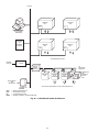
— For units connected into a CCN network, the timeclock
can be integrated into the overall building Energy Management System and be updated remotely.
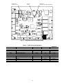
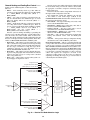
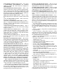
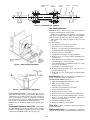
MAIN BASE BOARD (MBB) — See Fig 10. The MBB is
the center of the ComfortLink control system. The MBB contains the major portion of the operating software and controls
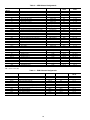
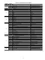
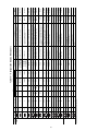
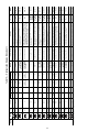
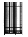
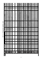
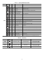
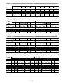
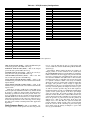
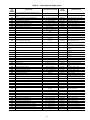
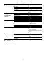
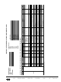
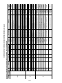
the operation of the unit. The MBB has 22 inputs and 11 outputs. See Table 2 for the inputs and output assignments. The
MBB also continuously monitors additional data from the
optional ECB1, ECB2, SCB, and CEM boards through the
LEN communications port. The MBB also interfaces with the
Carrier Comfort Network through the CCN communications
port. The board is located in the main control box.
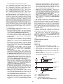
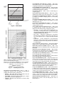
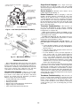
ECONOMIZER BOARD (ECB1) — The ECB1 controls the
economizer actuator and the power exhaust fans. The ECB1
operates the economizer motor using a digital communication
signal that also provides status and diagnostics for the economizer motor. See Fig. 11. The ECB1 also controls the operation
of the power exhaust motors and provides up to 6 stages of digitally sequenced power exhaust either based on the economizer
motor position or the building pressure. The board has 4 inputs
and 6 outputs. Details can be found in Table 3. The ECB1
board is located in an auxiliary box located at the end of the
unit behind the filter access door. The board also contains
a second LEN port than can be used with the accessory
Navigator display.
VAV BOARD (ECB2) — The VAV board (which is the same
hardware as the ECB1) is used to control the supply fan on
VAV units. See Fig. 11. It sends a 4 to 20 mA signal to the VFD
based on a supply duct pressure sensor connected to the board.
The board also accepts a signal from another pressure sensor
that monitors building pressure and controls the operation of
the optional modulating power exhaust motors. The board will
also be used on CV units with the optional building pressure
control feature and modulating power exhaust. This board is
also used to control a digitally controlled hot gas bypass solenoid with an integral orifice for use in low load applications.
This board is located in the auxiliary control box. Input and
output assignments are summarized in Table 4.
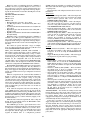
STAGED GAS HEAT BOARD (SCB) — When optional
staged gas heat is used on CV and VAV units, the SCB board is
installed and controls operation of the gas valves. See Fig. 12.
The SCB also provides additional sensors for monitoring of the
supply-air temperature. This board is located in the gas heat
section of the unit. The inputs and outputs are summarized in
Table 5.
CONTROL EXPANSION MODULE (CEM) — The optional
CEM is used to provide inputs for demand limiting, remote set
point and other optional inputs typically need for Energy
Management Systems. See Fig. 13. These inputs can be interfaced through the CCN communications. It is located in the
main control box. The inputs and outputs are summarized in
Table 6.
INTEGRATED GAS CONTROL (IGC) — One IGC is provided with each bank of gas heat exchangers (2 used on the size
020-050 units and 3 on the size 060 unit). The IGC controls the
direct spark ignition system and monitors the rollout switch,
limit switches, and induced-draft motor Hall Effect switch. The
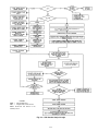
IGC is equipped with an LED (light-emitting diode) for diagnostics. See Table 7.
COMPRESSOR PROTECTION BOARD (CS) — This board
monitors the status of the compressor by sensing the current
flow to the compressors and then provides digital status signal
to the MBB.
MAJOR SYSTEM COMPONENTS
General — The 48/50A series package rooftop units with
electric cooling and with gas heating (48A units) or electric
cooling and electric heating (50A Units) contain the
ComfortLink electronic control system that monitors all operations of the rooftop. The control system is composed of several
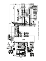
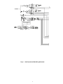
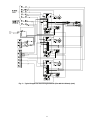
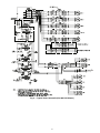
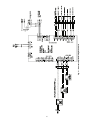
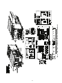
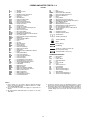
components as listed below. See Fig. 1-7 for typical control and
power component schematics. Figures 8 and 9 show the layout
of the control box, unit, and thermistor and transducer locations.
4