1
ASM-10/8 Installation and Operation Manual
Chapter 2 Installation and Setup
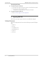
Opening the ASM-10/8 Case
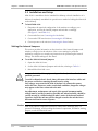
To reach the internal jumpers and switches of ASM-10/8, it is necessary to open its
case.
To open the ASM-10/8 case:
1. Disconnect all the cables connected to ASM-10/8.
2. Turn the unit over (bottom facing up).
3. Unscrew the four cover screws.
4. Turn the unit over (bottom facing down).
5. After the four screws released, remove the ASM-10/8 top cover by pulling it
straight up.
Setting the Internal Jumpers and Switches
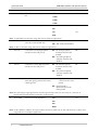
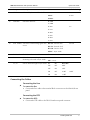
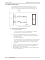
The internal jumpers and switches located on the ASM-10/8 printed circuit board
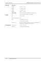
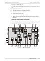
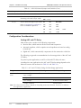
(PCB) are identified in Figure 2-1. Their numbers under heading "Item" in Table 2-1
correspond to the identification numbers shown in Figure 2-1.
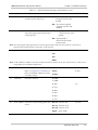
LEN
OFF
ON
OFF
ON
8 BIT ON=25%
9 BIT
10 BIT
11 BIT OFF=12.5%
11
S2(%)
70 1
6
2
54 3
CTS-DLY
RCV IMPD
150
300
600
HIGH
S4
OFF
OFF
ON
ON
12
0 ms
8 ms
64 ms
S3
13
10
CHAS GND
CONN
14
DIS
15
GND
RCV
XMT
S1
S2
S3
S4
XMT IMPD
0 dbm
-3 dbm
-6 dbm
-9 dbm
INT
EX
RCV
ASY
PIN 18
600
300
150
LOW
XMT LEVEL
XMT TIMING
EN DIS
DTE
PIN 21
SWITCH
2W/4W
CARRIER
EN DIS
2W 4W
CTRL ON
EN DIS
RPF
ON OFF
GND
AGC
Fuse
CTRL ON
1
2
3
4
5
6
7
8
9
Figure 2-1. ASM-10/8 PCB Layout
Installation and Setup
2-3