1
Trunk Mounting Cont.
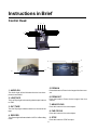
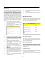
Connect the Control Console cable , rear Camera and
Mic cable, Antenna cable and the Power cable to the
rear of the vault. Bundle the cables to create a service
loop so that the vault can easily be unlocked, removed
from the base plate and cables disconnected.
Attaching the cables to the
rear of the vault.
Control Console
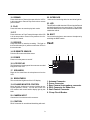
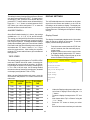
Remove the control head mounting plate from the control console (4 screws on front). Remove the sun visors inner
attachments (closest to the rear view mirror).Position the control
mounting plate between the sun visors such that when the control
box is attached, the monitor can be viewed from driver’s position.
Align the hole over the sun visor’s inner attachment holes and reinstall the sun visor attachments, making sure the control head mounting plate is captured by the attachments. If additional support is
desired (requires making holes in headliner), 3/4 inch self-drilling
screws can be used to attach the mounting plate to the secondary
metal under the headliner. Wait to mount the control box until the
end of the installation.
Note: If you have a ticket light (round light) added to your vehicle, you
have to use the ticket light adapter.
Attaching the Control head mounting plate
between the sun visors.
To determine wether or not you need the ticket light adapter, position the control box behind the light. You should
have at least 2 inches between the control box and window, but still be able to get to the monitor controls on top of the
control box. Most Ford Crown Victoria’s will not need this, most Chevy Caprices will.
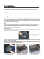
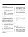
Antenna Mount
This is a common lip antenna. Position the antenna at the desired location on top of the trunk. For mounting see the
instructions enclosed with the antenna.
Note: If the Radio Frequency Interface is significant, a permanent 1/4 inch wave VHF antenna may be needed to
mount through the fender of trunk.
Rear Camera & Microphone
Position the camera and microphone to the desired location at the rear of the vehicle. For mounting, see the
instructions enclosed with the Rear Camera.
Interface Cable
This is the gray cable with a 4-pin connector on one end and the orange, black, blue, and white wires on the other end.
Route the interface cable from the control head to the fuse box. Start at the center of the headliner, to the driver side
of the central cable, leaving about 4 inches of the 4 pin plug end of the cable hanging down. Route across, under edge
of the headliner, down the door to the fuse box. Attach the orange wire to switched 12 V. Extend white wire to the
light box wire that gets 12 V when the overhead lights are activated. Attach the blue wire (+) and the black wire () to the siren. If the siren is AC instead of DC, you can use the same connections.
Note: For AC-The Blue wire is Hot, the Black wire is Neutral.
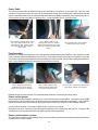
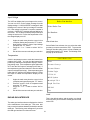
DB-25 Control Cable
This is the 25 foot DB-25 male to DB-25 male cable. Connect one side of the cable to the control head and other to
the vault. Route the cable through the backseat to the front of the car, up the front door post, along the front edge of
the headliner, to the middle of car. Leave about 4 inches hanging from the headliner. (Pictures of cables being routed
located on next page with Power Cable routing)
12