1
BBT1253 G_CDi Rg+Sys TS c08_07
25/6/07
09:21
Page 14
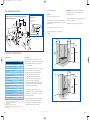
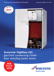
Greenstar CDi Conventional
Compartment installation
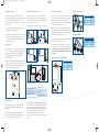
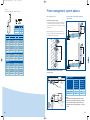
Condensate termination and route
External condensate pipework
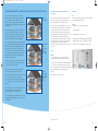
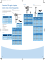
The appliance may be installed in any room, although
The condensate connection on Worcester appliances is in
All Worcester condensing boilers have within a syphonic
particular attention is drawn to the requirements of the IEE
22mm plastic. The pipe should be extended and directed
condensate trap. Rather than the condensate constantly
A Flow
22mm
regulations applicable and in Scotland the electrical
away from the appliance with a constant minimum fall of
dripping into the discharge pipe, the condensate is
B Gas inlet
22mm
collected into a trap which releases it in 100ml quantities.
C Return
22mm
provisions with respect to installation in a room containing
3 degrees or 50mm in every metre.
a bath or shower.
Pipework connections
This will help prevent freezing occurring.
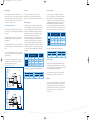
The condensate pipe can terminate into any one of five areas:
• The room in which the appliance is installed does not
Wherever possible the condensate discharge pipework
require a purpose provided air vent.
should be routed and terminated internally. Should this not
A
B
C
be possible, and the only available route is external, the
• If the appliance is installed in a cupboard or compartment
following conditions should be observed:
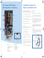
Greenstar CDi System
with dimensions that allow the minimum clearances
• The pipework length should be kept to a minimum and
shown in the siting of appliance section above, then no
Wall preparation
Pipework connections
the route as vertical as possible
ventilation is required.
Internal sink/
washing machine drain
Internal waste drainage system
• Where pipework could be subjected to extreme cold or
A Flow
22mm
B Gas inlet
22mm
C Return
22mm
wind chill, a weather proof insulation should be used.
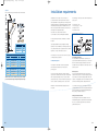
The drawing shows the new CDi wall mounting jig which
Alternatively, the condensate pipework could be
enables a simple and straightforward method of attaching
increased to a minimum 32mm without the requirement
the boiler to the wall surface. The new wall mounting
to insulate.
A
B
C
jig has additional optional fixing points and provides
improved engagement.
After fixing the jig to the wall, the appliance can be lifted
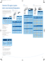
Pipework connections and casing dimensions
Soil and vent stack
External drainage system
Cabinet dimensions (mm)
C
onto the jig and the union connections tightened. The
A
750*
pipework can be routed behind the boiler without the
B
440
C
360
need for an additional wall spacing frame.
*760mm to top of casing front.
A
External condensate absorption point
(unsuitable for clay soil types)
A Condensate from boiler syphon/trap
B Sink with integral overflow
G 300mm x 100mm dia sealed
plastic tube
C 22mm dia plastic condensate pipe
H Ground level
D External drain or gully
J Drainage holes 50mm facing away
from building
E Internal soil and vent stack
F Serviceable condensate trap
(75mm min.)
B
K Limestone chippings
L Weather resistant insulation
Condensate disposal
Whilst all of the above methods are acceptable it is always
All condensing boilers generate condensate discharge
the best practise to terminate the condensate pipe via an
which needs to be piped away from the appliance via a
internal waste system. This will eliminate the need for any
plastic pipe.
external condensate pipe runs which can be susceptible to
freezing in extreme weather. Best practise is not to run
The amount of condensate generated depends on the
external condensate pipe any further than 3m. If it is
efficiency and operating status of the appliance. This can
necessary to run more than 3m externally increase pipe size
be up to 2 litres of condensate water an hour.
to 32mm.
14
15