1
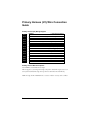
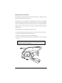
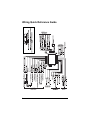
H1/8 BLACK (-) Chassis Ground Connection
Connect this wire to a clean, paint-free sheet metal location (driver kick panel) using a factory bolt
that DOES NOT have any vehicle component grounds attached to it. A screw should only be used
when in conjunction with a two-sided lock washer. Under dash brackets and door sheet metal are
not acceptable ground points. It is recommended that all security components be grounded at the
same location.
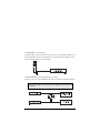
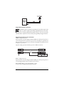
H1/10 BROWN (+) Siren Output
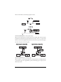
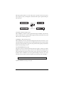
Connect this to the red wire of the siren. Connect the black wire of the siren to (-) chassis ground,
preferably at the same point you connected the control module’s black ground wire.
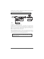
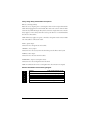
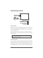
H1/11 RED (+)12V constant power input
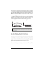
Before connecting this wire, remove the supplied fuse. Connect to the battery positive terminal or
the constant 12V supply to the ignition switch.
NOTE: Always use a fuse within 12 inches of the point you obtain (+)12V. Do not use the 15A
fuse in the harness for this purpose. This fuse protects the module itself.
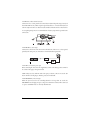
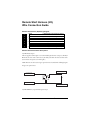
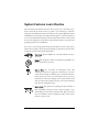
H1/12 RED/WHITE (-) 200 mA output
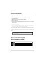
When the system receives the code controlling Channel 2, for longer than 1.5 seconds, the
RED/WHITE wire will supply an output as long as the transmission continues. This is often used
to operate a trunk/hatch release or other relay-driven function.
©
2003 Directed Electronics, Inc.
11