1
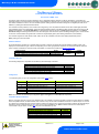
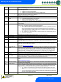
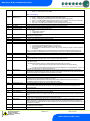
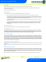
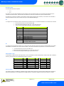
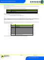
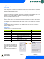
Mercury 3 M & E Installation Guide Viewing IO Apart from setting up the controller, you can also view the status of the inputs and outputs and controller states. From the function menu, select “I/O”, press enter. You can now scroll through the IO table as set out below. Inputs and outputs that do not apply to a particular controller type will be greyed out. Input / Output Table Number I-01 I-02 I-03 I-04 I-05 I-06 I-07 I-08 I-09 I-10 I-11 I-12 I-13 I-14 I-15 I-16 I-17 I-18 I-19 I-20 I-21 I-22 I-25 O-01 O-02 O-03 O-04 O-05 O-06 O-07 O-09 O-10 O-11 O-12 O-13 O-14 O-15 O-16 O-17 O-18 O-20 O-21 O-30 O-31 S-01 IO Range* o C ( oF ) Control Temp. Display temp. Air on Probe Air off Probe Evaporator Probe Suction Line Probe Superheat Logging Probe Defrost Probe Plant Fault (1) Case Clean Door Sensor Person Trapped Plant Fault 2 (Integral) External Defrost (EEV) Monitor Probe Remote Evap Temp MOP External Defrost (Mechanical Valve) Hub Trim Level (EEV) Divide Input Remote Pressure Local Pressure Local Calc temp Load Shed Liquid Line Valve Suction Line Valve Compressor A Compressor B Defrost Control Lights Case Fans EEV Opening Last Def. Time Last Def. Length Last Def. Ctrl Temp. Last Def. Type Suction Line Valve/Trim Heaters Alarm Relay (Relay3) Alarm Relay (Relay4) Remote Relay (Relay 4) Run Time Door Open Time Door Open Length Set Point Offset Trim Off Period Control State Step Units -42 to 128 (-43.6 to 262) -42 to 128 (-43.6 to 262) -49 to 128 (-56.2 to 262) -49 to 128 (-56.2 to 262) -42 to 128 (-43.6 to 262) -42 to 128 (-43.6 to 262) -30 to 60 (-54 to 108) -49 to 128 (-56.2 to 262) -49 to 128 (-56.2 to 262) 0 (OK), 1 (Alarm) 0 (Off), 1 (On) 0 (Closed), 1 (Open) 0 (OK), 1 (Alarm) 0 (OK), 1 (Alarm) 0 (Off), 1 (On) -49 to 128 (-56.2 to 262) -49 to 128 (-56.2 to 262) 0 (Off), 1 (On) 0 (Off), 1 (On) 0.1 0.1 0.1 0.1 0.1 0.1 0.1 0.1 0.1 Deg Deg Deg Deg Deg Deg Deg Deg Deg 0 to 100 0 to 100 -3.4 to 180.0 -3.4 to 180.0 -49 to 128 (-56.2 to 262) 0 (Off), 1 (On) 0 (Off), 1 (On) 0 (Off), 1 (On) 0 (Off), 1 (On) 0 (Off), 1 (On) 0 (Off), 1 (On) 0 (Off), 1 (On) 0 (Off), 1 (On) 0 to 100 00:00 to 23:59 00:00 to 03:00 -42 to 128 (-43.6 to 262) 0 (None), 1 (Internal), 2 (External), 3 (Network), 4 (Display), 5 (Timed) 6 (Forced), 7 (Skipped) 0 (Open/Off), 1 (Closed/On) 1.0 1.0 0.1 0.1 0.1 0 (Unused), 1 (OK), 2 (Alarm) 0 (Unused), 1 (OK), 2 (Alarm) 0 (Off), 1 (On) 0 – 128 K Hours 00:00 to 23:59 00:00 to 03:00 -49 to 128 (-56.2 to 262) 00:00 to 05:00 0 (Stabilise),1 (Normal), 2 (Defrost Min), 3 (Defrost Max), 4 (Drain Down), 5 (Fan Delay), 6 (Recovery), M Type 1&2 M Type 3&4 M Type 5&6 0.1 0.1 Deg Deg % % Bar Bar Deg E Type 3&4 E Type 5&6 0.1 0.1 % hh:mm hh:mm Deg 1 0.1 00:01 k hrs hh:mm hh:mm Deg. mm:ss Warning Ensure that all power is switched off before installing or maintaining this product Revision 1.0 Page 22 of 29 www.resourcedm.com Please Note