1
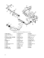
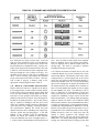
Position hoses (2) over beads and secure with
clamps(1).
8-24.
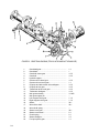
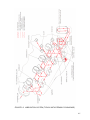
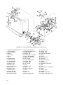
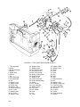
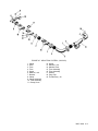
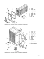
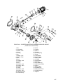
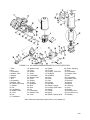
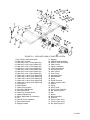
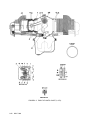
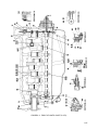
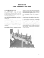
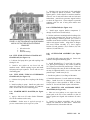
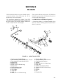
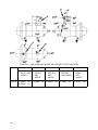
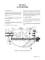
INDUCTION SYSTEM, IO-520-E (See
Figure 4-8).
a. Push a new hose (2) on either end of center intake
tubes. Slide one hose clamp (11) to a point midway
on overlapping portion. Turn each clamp so that a
screwdriver can be aligned with its screw and yet clear
of the stand when tube is installed. Tighten only
enough to hold clamp in position.
b. Place a hose clamp (11) on each end of cylinder
intake tubes so it faces center tube. Push end tubes
into hoses previously installed on center intake tubes.
Work hose clamps over ends of hoses, but not past
bead. Do not tighten at this time.
c. Push a hose (2) on each front intake tube, and hose
(2A) on each rear intake tube and install a clamp (1)
on the overlapping portion behind the tube bead of the
rear intake tube. Tighten these clamps.
d. Lay a new gasket (17) on intake flange of each
cylinder. Position each assembly of tubes and hoses
on proper bank of cylinders and adjust each tube so it
seats squarely on cylinder port.
e. Attach each intake flange to its cylinder with four
sets of attaching parts (12, 13, 14). Position clamp on
two center hoses on each side tube beads and tighten.
f. Push hose clamp on elbows (3, 4) and push elbows
into connecting hoses of rear intake tubes. Position
clamps and tighten only enough to hold tubes.
g. Install clamp (8) and bracket (7) on balance tube
(10). Push tube ends into connecting hoses installed
on front intake tubes. Position bracket and secure to
sump with attaching parts (5,6). Position clamp
assembly (9) over tube beads and tighten. Turn
engine upright.
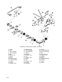
(18, 19). Insert sleeve (37) and bushings (36) in
support bracket (35). Secure support bracket to
throttle body with bolt (30), and nut (29).
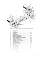
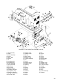
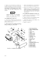
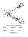
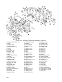
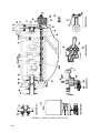
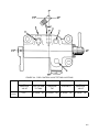
8-25. FUEL INJECTION SYSTEM, IO-520-A
(See Figure 4-1).
a. Attach shroud assembly (49) to fuel pump and
vapor separator (44) with speed nuts (47), screws (46)
and spring (45).
b. Connect fuel hoses from fuel supply to fuel pump,
from fuel pump to fuel control metering unit and fuel
return line from fuel control metering unit to fuel
pump; also, fuel supply line from fuel control
metering unit to fuel manifold valve.
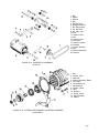
8-26.
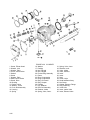
4-5).
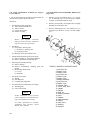
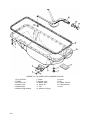
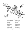
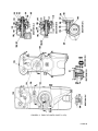
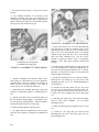
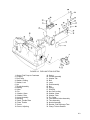
MAGNETO DRIVE GEARS (See Figure
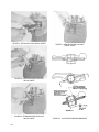
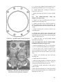
a. With engine in upright position, insert one pressed
steel retainer (22) into each gear hub slot.
b. Cover each of four new rubber bushings with a
film of Gredag No. 44 and insert two bushings (21)
into each retainer, rounded long edges first.
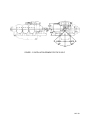
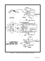
c. Turn the crankshaft to the No.1 cylinder advance
firing angle as described in the following paragraph.
Lubricate each magneto drive gear shaft and teeth (20)
and insert into bushings (15). Observe the shaft ends
from the rear as they are carefully pushed through the
adapter oil seals to make sure the seal lips are not
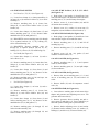
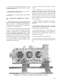
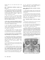
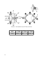
reversed or damaged. Mesh the magneto drive gears
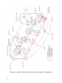
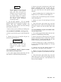
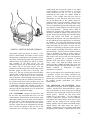
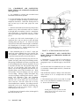
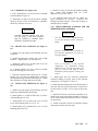
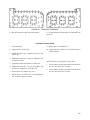
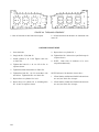
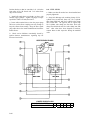
to the idler gear to the approximate position shown in
Figure 8-14. These positions will vary slightly due to
differences in magnetos and gears.
h. Secure support bracket (35) to upper magneto drive
adapter studs and oil pump cover and secure with
attaching parts (31, 32).
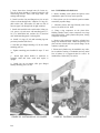
i. Position air throttle assembly on bracket (25) and
secure with attaching parts (23, 24). Place hose clamp
(1) over each hose (2A) and work hoses onto throttle
body. Position and tighten clamps. Secure support
bracket (35) to throttle body with attaching parts (28,
20, 11) and sleeve (27) and grommet (26). Attach
bracket (33, 34) to throttle body with attaching parts
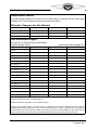
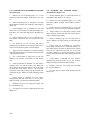
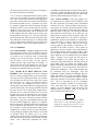
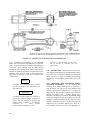
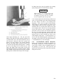
FIGURE 8-14. POSITION OF MAGNETO COUPLINGS.
8-12
MAY 1980