1
INSTALLATION
1. Remove all packing and foreign material
from unit.
2. Check blower wheel for free rotation.
3. Check copper lines, coil etc for internal or
hidden damage. Maintain caps and plugs
until ready for connection to system.
4. In an attic installation where unit is resting
on the attic floor, a suitable isolation pad or
other vibration isolation should be provided
to minimize equipment sound transmission
to the living area.
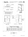
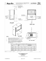
5. The fan coil requires service clearances as
shown in Figures 8 and 9. Units are approved for 0” (zero inches) of clearance.
Units are designed for vertical (upflow or
downflow) airflow discharge only.
6. Mount unit on accessory legs (leg kit accessory) or field-provided stand. WARNING! Make sure to allow at least 4.5”
below the unit for the condensate drain
trap!
7. Mount Install condensate drain. See section “CONDENSATE DRAIN”.
8. Attach discharge and return ductwork. See
section “Placing Unit in Ductwork.”
9. Connect refrigerant liquid and suction piping to unit (DX coil). NOTE: Size and install per condensing unit manufacturer’s
recommendations.
10. Connect chilled water supply and return
piping to unit (Chilled Water coil).
CAUTION: Protect cabinet and internal
piping by wrapping each pipe with a wet
cloth while brazing.
The unit should be supported by a suitable
floor surface. Unit is not intended to be
suspended from a ceiling or roof deck.
WARNING: Insure that supporting
structure is adequate for the loads
being applied. Consult structural design professional if required.
Before installing any unit, the installer must
determine that the weight of the unit can be
safely supported by the floor joists, rafters,
ceiling, etc. Care should be taken to insure
that floor stand or other mounting surface is
located so as to not block the access doors,
interfere with the electrical, mechanical, or
drain functions of the units.
WARNING: Disconnect and Lock Out all
incoming power sources before connecting
to electrical service.
Attach L1 and L2 to motor neutral and
speed wire lead leads as shown on wiring
diagram on unit front panel. Refer to
nameplate for FLA, MCA and MOPD.
Units with field installed electric heater accessory may be equipped with fan relay.
035-000040-001
Page 5 of 18
DVA IOM 1.3 08-18-2014