1
TM 11-5820-670-30
1-58. RECEIVER-TRANSMITTER INTRAUNIT CIRCUIT FUNCTIONING (CONT)
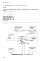
METERING CIRCUIT
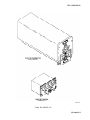
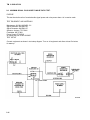
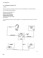
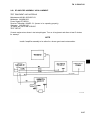
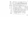
See FO-12, receiver-transmitter, Radio RT-823/ARC-131, while reading this section.
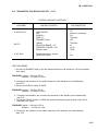
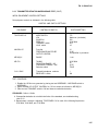
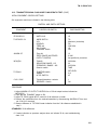
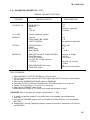
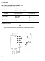
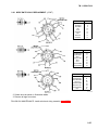
Test Switch S9601 on the receiver-transmitter front panel selects various operating voltages and
outputs and applies them through series resistances when necessary to TEST METER M9601. The test
meter displays these voltages to provide a quick check of radio set performance. TEST SWITCH S9601
positions are marked with numbers 1 through 6.
With TEST SWITCH S9601 in position 1, +24 volts are applied to the meter. The meter requires 100
microampere for full scale deflection, therefore +24 volts applied across R9606 (470 K
produces half-scale deflection.
In position 2, +16 volts are applied across R9605 (300 K
mately half-scale deflection.
) where a normal reading is approxi-
In position 3, a portion of agc voltage is applied to the meter through R9604. Resistor R9604 limits the
meter current to provide approximately half-scale deflection for normal agc levels.
In position 4, a portion of rf forward power is applied to the meter. Normal forward power provides
approximately half-scale deflection.
In position 5, a portion of rf reflected power is applied to the meter. Normal reflected power must not
exceed quarter-scale deflection.
1-59. CONTROL, RADIO SET C-7088/ARC-131 FUNCTIONING.
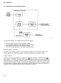
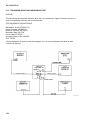
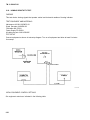
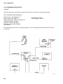
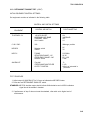
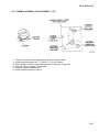
All radio set operator controls are located on Control, Radio Set C-7088/ARC-131. The controls
include the following:
Mode control switch S9105
Squelch control switch S9106
Volume control R9103
Frequency select controls S9101, S9102, S9103, S9104.
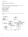
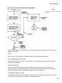
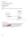
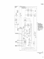
For an explanation on operation of these controls, see FO-13 while reading this paragraph.
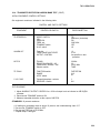
MODE CONTROL SWITCH S9105
The mode of operation is determined by the mode control switch. The switch also controls the
application of primary power to the radio set. Mode control switch S9105 is a four position rotary switch
with six sections (front and rear). Operating power is applied to the receiver-transmitter when S9105
is set to any position except OFF.
In transmit-receive (T/R) position, the radio set operates in normal communication mode and automatically switches from transmit to receive condition or vice versa when the microphone push-to-talk
button is pressed or released.
1-63