1
INSTALLATION INSTRUCTIONS
WARNING: Always keep the caution sheet (SPECIAL INSTRUCTIONS AND WARNINGS) close to the oven for
your reference.
1) Remove all packing materials from the inside of the
oven cavity. Remove all the blue protective film
from the outside of the oven.
2) Check the oven carefully for any sings of damage.
3) Place the oven on a flat, level surface strong enough
to support the oven's weight plus the heaviest item
likely to be cooked.
4) Ensure there is a minimum free space above the
oven of 25 cm.
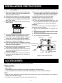
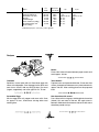
6-6) Remove the screw (a) holding the mounting plate B
to the rear cabinet of the oven B. And remove the
mounting plate B from the oven B. See the figure A.
6-7) Install the screw (a) to its position again.
6-8) Remove the screw (c) from the oven A.
6-9) Remove the screw (d) from the oven B.
6-10) Turn the removed mounting plate B over and
then using the removed screw (c) and (d), attach
the mounting plate B, as shown in the figure A.
WARNING:
In case where two ovens are installed together by
placing one on top of another,
1) Use the two mounting plates for fixing the two
ovens.
2) Make sure that the power supply cord is not caught
between the two ovens.
3) Do not install more than one oven on top of another.
4) Do not lose the removed screws.
25 cm
5) Securely connect the plug of the oven to a standard
earthed (grounded) household electrical outlet.
6) Two ovens can be installed together by placing
Oven B
Screw (a)
one on top of another. Follow these instructions.
6-1) Place the oven A and position the oven B on top of
the oven A as shown in the figure A.
Reat Cabinet
6-2) Remove the single screw (a) holding the mounting
plate A to the rear cabinet of the oven A. And Mounting plate A
remove the mounting plate A.
Screw (d)
Screw (b)
6-3) Remove the single screw (b) from the rear cabinet
of the oven B, as shown in the figure A.
6-4) Reinstall the mounting plate A to the rear cabinet
Screw (c)
of the oven B with the single screw (b) removed, as
Screw (a)
Mounting plate B
shown in the figure A.
Oven A Rear cabinet
6-5) Hold the mounting plate A to the rear cabinet of
the oven A with the single screw (a), as shown in
the figure A.
Figure A: How to fix two ovens
ACCESSORIES
Check to make sure the following accessories are provided:
Manuals and others
• Operation manual
• Menu sticker
Enter cooking times or dish names in this sticker and attach to the control panel.
• Caution sheet (SPECIAL INSTRUCTIONS AND WARNINGS: part code TCAUHA257WRR0)
NOTE:
• When you order accessories, please mention the two items: part name and model name to your dealer or
SHARP authorized service agent.
• The model name is printed on the cover of this operation manual.
3